


 English
 Français
 русский
 عربى
 Español
 Deutsch
Tel
+86 186 2508 0683

A packaging machine needs a 50 mm vertical lift, 40 cycles per minute, and a 6 kg tool head. The first actuator chosen from a catalog has enough rated force and the right stroke, so the prototype works. Eight months later, field units begin losing position after long shifts, grease migrates past the seal, and the motor driver trips when ambient temperature climbs above 40 C. The machine builder did not miss a single obvious number on the datasheet. The problem was that the specification focused on force and stroke while the real application was defined by duty cycle, moment load, thermal margin, control integration, contamination, and production consistency.
That is the core challenge in specifying electric linear actuators for OEM equipment. An actuator is rarely a standalone commodity in an OEM machine. It is a motion axis inside a system that must meet a cycle time, fit a crowded envelope, survive a plant environment, communicate with a controller, pass safety review, and remain repeatable across thousands of units. The useful approach is to specify the axis as a system, then use the actuator supplier to prove the critical assumptions with test data rather than catalog headlines.
OEM engineering teams usually begin with a load diagram, a target cycle time, and a mechanical envelope. That is the right starting point, but the information must be converted into an actuator duty profile. A force number without acceleration, dwell, orientation, and lifetime target is not a specification. A stroke number without mounting stiffness, overhung load, and end-of-travel conditions is only a space claim.
For a horizontal axis, the required actuator force is approximately the sum of acceleration force, friction, and any process force. For a vertical axis, gravity becomes part of the continuous load and changes the holding, braking, and safety requirements. A simple estimate looks like this: required force equals moving mass times acceleration, plus friction, plus the gravity component along the axis. That estimate is only a starting point because acceleration is often limited by the actuator's own moving mass, screw critical speed, belt stretch, or the machine frame. If the actuator weighs 12 kg and the tool head weighs 6 kg, the effective moving mass may be 18 kg before payload variation. Add a 10 kg workpiece and the acceleration force changes dramatically.
Consider an 80 kg gantry carriage that must accelerate at 0.5 g. The inertial force alone is about 392 N before friction and process load. If the actuator is mounted at an angle, the gravity component adds or subtracts force depending on direction. If the center of gravity is 150 mm from the axis, the moment load at the carriage becomes 392 N times 0.15 m, or about 59 Nm. That moment may matter more than the axial force because it loads the guide, bearing, and seal. Many catalog force ratings assume a centered, purely axial load. OEM machines rarely provide that ideal condition.
The practical remedy is to give the supplier a short motion profile: moving mass, payload range, orientation, acceleration, velocity, dwell, stroke, cycle count per shift, expected life, and mounting distance. Ask for continuous force at the actual ambient temperature, not only peak force for a few seconds. Ask for moment and radial load limits at the required stroke. Ask what happens at the end of stroke if the machine crashes or stalls. The answers expose whether the actuator is being applied inside its real capability or merely inside its advertising.
An electric linear actuator may be rated for 5 kN, but that number could describe a short-duration stall condition, a static holding condition, or a peak that requires a larger frame and reduced life. OEM equipment needs a load case matrix. At minimum, separate normal running load, peak acceleration load, process load, stall or jam load, and shipping or installation load. Each case has a different duration and a different consequence.
Bending moments are often the hidden constraint. A load cell, gripper, welding torch, or end effector extends the center of gravity away from the actuator axis. The resulting moment can cause guide wear, seal deformation, position error, and noise. In a vertical lift, an offset load may also create a tipping moment that the machine frame must resist. If the actuator is selected only by axial force, the bearing may be overloaded long before the motor reaches its torque limit.
Shock is another gap between datasheet and machine. A press, stamping station, or transfer mechanism can generate impact loads at end of stroke. Even a well-damped axis may see repeated shock if a workpiece stops against a hard stop. The actuator supplier should know whether the application includes external stops, crash conditions, or manual override. A design that survives a gentle laboratory profile may fail when an operator jogs the axis into a fixture.
For dusty or high-moment applications, a heavy-load dustproof inline electric cylinder is a more realistic starting point than a standard inline unit because the guide and sealing system are intended for off-axis loads and contaminated environments. That does not remove the need to calculate the moment, but it gives the specification a better mechanical foundation. The key is to request load curves at the actual stroke and mounting orientation, not just a single maximum value.
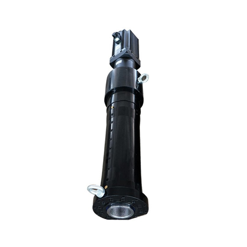 Heavy-Load Dust-Proof Inline Electric CylinderHeavy-duty inline electric cylinder for dusty, high-moment applications, with dust-proof sealing and customizable stroke; suitable for checking load curves and duty-cycle thermal margins.View Product →
Duty cycle is where many OEM actuator specifications become optimistic. A machine may move for 1.5 seconds and dwell for 0.5 seconds, which sounds like a 75 percent duty cycle. But the actuator does not heat uniformly. The motor, screw nut, guide, seal, and drive electronics have different thermal time constants. A high cycle rate with short moves may heat the motor more than a long move with low acceleration. A vertical axis may hold torque continuously while stationary, adding heat even when the axis is not moving.
Instead of asking whether an actuator can run at 40 cycles per minute, calculate the root-mean-square force or torque over a representative cycle. Compare that with the actuator's continuous rating at the installed ambient temperature and mounting condition. Consider whether the actuator is mounted in open air, inside a cabinet, behind a guard, or near a heat source. A unit rated for 25 C ambient may need derating at 45 C, especially when the electronics are enclosed.
Life is also a stack of wear mechanisms, not one number. The screw nut has an L10 life based on load and travel; the guide has a load and moment life; the motor has bearing and winding limits; the grease has temperature and contamination limits; the seal has friction and chemical exposure limits. A supplier may quote 10 million cycles, but the number is only meaningful with the stroke, load, speed, duty cycle, and environment attached. For OEM equipment, ask for the basis of the life calculation and the assumed maintenance interval.
Thermal margin is particularly important when the enclosure is compact. Sealed actuators protect against dust and water but may dissipate heat less effectively. High-temperature environments reduce grease life and motor torque margin. A high-temperature-resistant heat-dissipating electric cylinder is designed to address this condition, but the machine builder still needs to confirm the ambient profile, heat soak at startup, and whether forced air or a heat shield is required. A product intended for elevated temperature is not a substitute for a thermal calculation.
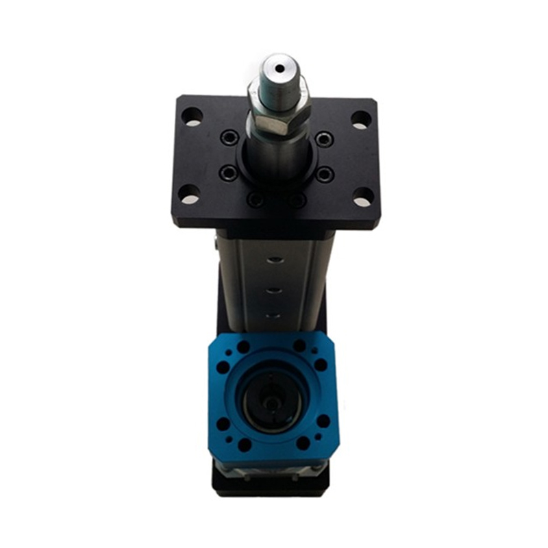 High-Temperature Resistant Heat-Dissipating Electric CylinderWide-temperature electric cylinder for high-temperature equipment, featuring independent motor heat dissipation and high-temperature sealing; confirm ambient profile and heat-soak conditions.View Product →
Long stroke and high speed pull the specification in different directions. A ball screw actuator may be excellent for thrust and rigidity, but critical speed and screw whip limit the maximum speed as stroke increases. A belt-driven actuator may be better for long travel and high speed, but it introduces compliance, belt stretch, and different maintenance considerations. A rack-and-pinion unit may suit very long strokes and high speed, but the mounting and lubrication requirements change. A telescopic actuator can retract into a short envelope and extend over a long distance, but the nested stages add cost and require careful guidance.
The OEM machine envelope is often fixed before the actuator is selected. That creates risk. A folded or parallel-mounted actuator may fit a shorter overall length, but the motor and belt housing may protrude into service access. An inline actuator may be compact around the axis but too long at the rear. A telescopic unit may provide a clean retracted length but needs a larger extended clearance. The specification should include not only the stroke but also the retracted length, extended length, motor orientation, cable exit, mounting hole pattern, service clearance, and removal path.
Speed should be specified as a profile, not a single maximum. The actuator must accelerate the load, move at a controlled velocity, decelerate, and settle within the required time. If the controller uses trapezoidal motion, the acceleration and deceleration segments contribute to heating and mechanical stress. If the machine needs smooth interpolation, the actuator stiffness and feedback resolution may matter more than top speed. A high-speed catalog rating may be reached only at no load or with a specific controller and voltage.
| OEM requirement | What to verify | Common specification gap |
|---|---|---|
| High thrust in a compact frame | Continuous force at ambient temperature, screw life, guide moment capacity | Using peak force as if it were continuous force |
| Long stroke at high speed | Critical speed, belt or screw resonance, support guidance, end damping | Checking speed only at short stroke or no load |
| Short retracted length | Extended clearance, stage rigidity, seal protection, cable path | Forgetting service access and motor protrusion |
| Clean machine appearance | Mounting stiffness, cover design, cable routing, noise path | Treating the actuator as a drop-in part after the frame is frozen |
OEM engineers often ask for positioning accuracy when the real requirement is repeatability, or vice versa. Accuracy is how close the axis gets to the commanded position. Repeatability is how consistently it returns to the same position. Backlash, screw lead error, belt stretch, guide clearance, frame deflection, encoder resolution, and control tuning all affect the result. An actuator with excellent repeatability may still need external feedback or a home routine if absolute position is required.
Stiffness is another hidden specification. A belt-driven axis may be fast and clean, but the belt acts as a spring between the motor and carriage. Under a changing process force, the carriage can deflect even when the encoder is mounted on the motor. A ball screw axis is generally stiffer, but the nut, bearing block, and mounting plate still contribute compliance. If the machine uses a force-controlled process, such as press fitting or compliant assembly, the actuator and load cell must be specified together. Otherwise the force reading may include friction and structural deflection rather than the actual process force.
In semiconductor manufacturing and other precision assembly equipment, the specification may also include cleanroom compatibility, particle generation, vacuum or low-outgassing requirements, and thermal stability. A standard actuator with exposed grease and a painted finish may not be suitable. The machine builder should ask for the materials, lubrication, surface finish, and cleaning compatibility of the exact configuration. This is one reason to involve the supplier early: a small change in seal material or lubrication can affect both particle generation and service life.
Precision claims should be tied to a measurement method. Ask where the measurement is taken, at what load, at what speed, at what temperature, and after how many cycles. A repeatability figure measured at the motor encoder with no load is not the same as a figure measured at the tool center point with a hot screw and a side load. For OEM equipment, the acceptance test should match the machine's actual measurement point.
Applications in semiconductor manufacturing often expose these gaps quickly because the process window is narrow and the cost of unscheduled downtime is high. The actuator specification should state the allowable position error over the working stroke, the warm-up behavior, and the recovery method after a fault. Precision is not a catalog column; it is a system property.
An OEM machine builder may buy the actuator from one supplier and the drive from another. That can work, but it increases the integration burden. The motor's voltage constant, torque constant, encoder type, hall sensor configuration, brake option, and thermal sensor must match the drive. The controller must support the required motion profile, feedback resolution, and safety function. If the actuator is supplied as a complete unit with a matched drive, the specification should still define the interface to the machine controller: discrete I/O, analog command, pulse and direction, EtherCAT, CANopen, PROFINET, or another fieldbus.
Voltage architecture is a common OEM decision. A 24 V or 48 V DC actuator may simplify power distribution and battery operation, but higher force at high speed may require a larger current and thicker cables. A 230 V or 400 V AC servo solution may provide more power density and regenerative capability, but it changes the cabinet, safety, and wiring requirements. The machine builder should compare total system cost, not just actuator cost. A lower-cost actuator that requires an oversized power supply, extra braking resistor, or custom cable can be more expensive in production.
Feedback choice affects both performance and cost. A potentiometer may be adequate for simple position indication, but it wears and has limited resolution. Hall sensors can provide commutation and coarse position. An incremental encoder provides fine resolution but needs homing. An absolute encoder simplifies startup and recovery but adds cost. Limit switches may be sufficient for end-of-travel protection, but they are not a substitute for a controlled motion profile. The specification should define what happens after power loss, after an emergency stop, and after a jam. A vertical axis may require a brake and a controlled stop sequence. A horizontal axis may need regenerative energy management if the load decelerates quickly.
Safety integration also belongs in the actuator specification. If the axis creates a crushing hazard, the machine builder must decide whether safety is achieved by guard interlocking, safe torque off, safe speed monitoring, or mechanical limiting. The actuator supplier should provide the motor and brake data needed for the risk assessment, including brake holding torque, release time, and wiring diagrams. A certificate alone does not make the axis safe; the machine design must define the safety function and validate it.
IP ratings are useful, but they are often misunderstood. IP65 means protection against dust ingress and water jets. IP68 means protection against continuous immersion under specified conditions, which must be defined by the supplier. Neither rating automatically covers steam cleaning, chemical washdown, high-pressure spray at close range, condensation, or long-term submersion at pressure. An OEM machine used in food processing, outdoor equipment, or chemical handling may need a sealing system designed for the actual cleaning cycle, not just a generic splash rating.
Seals also create friction and heat. A heavily sealed actuator may require more motor torque and may run hotter than an open unit. If the machine uses washdown chemicals, the seal material must be compatible. If the machine operates in a cold environment, the seal may stiffen and increase breakaway force. If the machine operates in a humid environment, condensation inside the actuator or cable connector can cause failures even when the external IP rating is high. The specification should include the cleaning method, chemical list, ambient humidity, and temperature range.
For equipment that is exposed to splashing water or routine washdown, an IP65 splashproof waterproof electric cylinder may be a practical starting point. For equipment that is submerged or exposed to temporary flooding, a higher-protection configuration and a clearly defined immersion condition are needed. The machine builder should confirm the mounting orientation because a seal that works with the actuator shaft horizontal may behave differently when the shaft points upward and water pools at the rod seal.
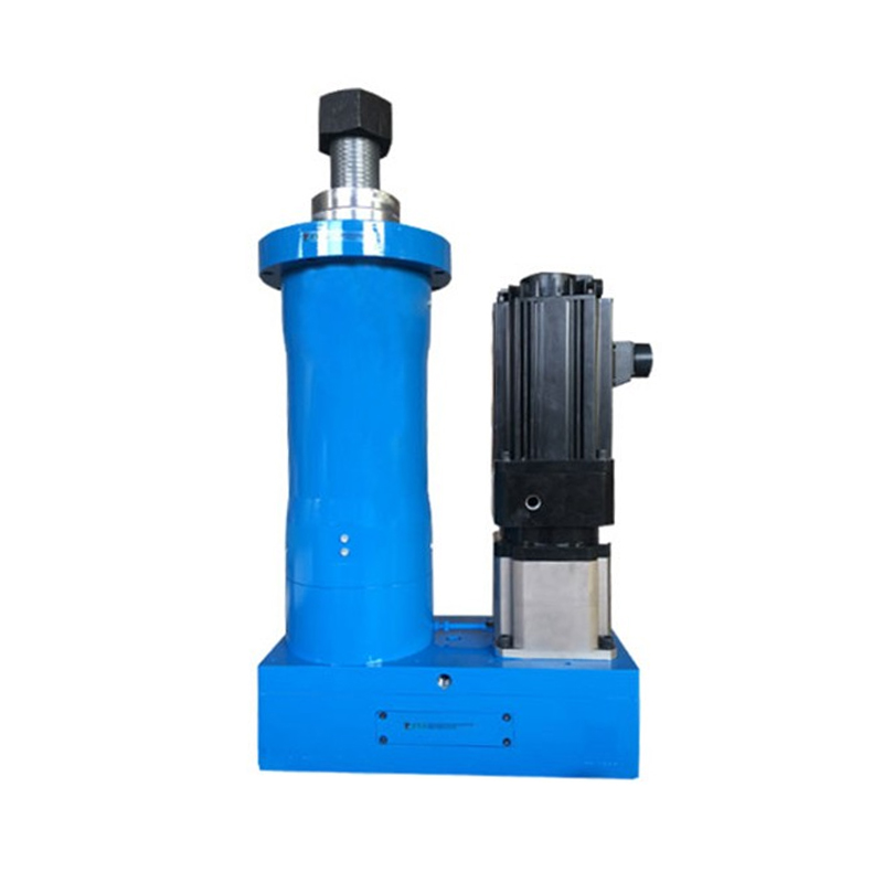 IP65 Splash-Proof Waterproof Electric CylinderIP65 electric cylinder with waterproof sealing and dust cover for splash-prone environments; check mounting orientation and actual exposure conditions before selection.View Product →
Hazardous-area applications add another layer of specification. An actuator used in a flammable atmosphere may require explosion protection, temperature class verification, appropriate cable glands, and a certificate that matches the installation. The machine builder cannot simply choose a “sealed” actuator and assume it is acceptable. The area classification, gas or dust group, temperature class, and purge or enclosure strategy must be defined before the actuator is selected. The same principle applies to equipment that must survive caustic cleaning, salt spray, or outdoor UV exposure. The enclosure, paint, seals, rod material, and fasteners all need to match the environment.
Extreme temperature is a lifecycle issue, not just a startup issue. A cold-resistant alloy and low-temperature lubrication may be needed for equipment that starts at minus 20 C or below. A heat-dissipating design may be needed for equipment near furnaces, ovens, or process heat. In both cases, the actuator's force rating must be derated and the control cabinet may need heating or cooling. The machine builder should provide a temperature profile over a full shift, including heat soak when the machine is idle and the surrounding equipment is still hot.
One practical mistake is to specify the actuator for the average ambient temperature but ignore the local hot spot near the motor. Another is to assume that a high-temperature actuator can be mounted in any orientation without derating. The supplier should review the installation drawing and the duty profile together. If the application includes both high temperature and a high cycle rate, the thermal margin may be the deciding factor between two actuators with similar force ratings.
Noise is often treated as a late-stage problem, but it can be a specification requirement from the beginning. A linear actuator can generate motor whine, screw whine, belt resonance, guide rattle, seal friction, and end-stop impact. The dominant source depends on speed, load, mounting stiffness, and the structure that carries the actuator. A unit that is quiet on a test bench may be loud when bolted to a thin sheet-metal frame that acts as a drum.
OEM equipment may need to meet a workplace noise limit, a customer perception target, or a measurement standard at the operator position. The specification should state the measurement distance, operating condition, and acceptable sound pressure level. It should also distinguish steady-state noise from transient noise during acceleration and deceleration. A high-speed move may be acceptable in a guarded area but unacceptable near an operator station. If the machine runs at night in a residential area, the noise target may be tighter than the internal factory standard.
Vibration can also affect fasteners, cable life, and sensor reliability. A long-stroke actuator with a high overhung load may vibrate at certain speeds. A belt-driven axis may have a resonance that changes with stroke. The machine builder should ask for the actuator's natural frequency, belt tension maintenance, and recommended mounting stiffness. If the actuator is mounted on isolation pads, the pads may improve noise but reduce positioning stiffness. That trade-off should be tested on the actual machine frame, not only on a supplier test stand.
A datasheet is a starting point, not a validation report. OEM equipment needs a design verification plan that reproduces the production duty profile with margin. The plan should include normal operation, maximum payload, minimum payload, voltage variation, ambient temperature extremes, contamination exposure, and fault conditions. If the machine is expected to run 20,000 hours, the actuator test should either run long enough to expose wear or use an accelerated profile with a justified model.
Thermal testing is especially important. Run the actuator through a complete machine cycle inside the actual enclosure, with the actual driver and cable length. Measure motor temperature, screw nut temperature, and controller temperature. Then run a heat soak at the maximum ambient temperature and repeat the cycle. Many failures appear only after the system has reached thermal equilibrium. A short laboratory run at room temperature can miss grease migration, seal softening, and drive derating.
Ingress testing should match the cleaning and operating environment. If the machine is washed daily, the test should include the same spray angle, pressure, temperature, and chemical concentration. If the machine operates in a dusty plant, the test should include the actual dust type and concentration. If the actuator has a breather or cable gland, those components should be included in the test because they are often the first path for water or dust.
Mechanical validation should include end-of-stroke impact, jam recovery, manual override, and emergency stop. The machine builder should verify that the actuator does not backdrive unexpectedly, that the brake holds the load, and that the controller can recover without losing position. If the actuator uses an absolute encoder, verify the startup behavior after a power interruption. If it uses an incremental encoder, verify the homing routine under load. These tests are more valuable than a general “life test” certificate because they reproduce the failure modes that matter to the OEM.
Finally, validation should include production variation. A prototype actuator may be hand-built and carefully adjusted. Production units may have normal tolerance variation in screw lead, belt tension, seal friction, and sensor alignment. The machine builder should test at least three units from different production lots and confirm that the machine's acceptance criteria still pass. If the machine requires a special calibration for each actuator, that calibration belongs in the production process, not in a service manual.
OEM equipment programs carry commercial risks that are not visible in a force calculation. A supplier may quote a attractive prototype price but apply a higher minimum order quantity, a long lead time, or a significant engineering charge for the production configuration. The machine builder should ask for the price break at the forecast volume, the lead time at that volume, the minimum order quantity, the warranty terms, and the cost of spare parts. It should also ask what happens if the forecast changes by 30 percent in either direction.
Documentation is part of the product. OEM machines often require drawings, bill of materials, calibration certificates, test reports, material declarations, and change notifications. If the actuator is used in a regulated industry, the supplier may need to provide traceability, PPAP-style documentation, or a quality agreement. The machine builder should confirm who owns the tooling, who controls the firmware, and how software changes are communicated. A silent change in grease, seal material, or encoder supplier can create a field failure that is difficult to diagnose.
Second-source strategy is another challenge. A custom actuator may be difficult to duplicate because the mounting interface, controller, and firmware are tightly coupled. The machine builder should decide whether a second source is required for risk mitigation or whether a single supplier with a validated continuity plan is acceptable. If a second source is required, the specification must be detailed enough to allow a true comparison, including load curves, interface dimensions, control protocol, and test methods. A “drop-in replacement” claim should be verified with a form, fit, and function test.
Applications in automotive manufacturing often illustrate this point because production lines cannot tolerate unannounced changes. A supplier that understands the OEM environment will provide a change notification process, batch traceability, and a clear escalation path. That is not a substitute for good engineering, but it reduces the risk that a validated actuator behaves differently six months after launch.
The following checklist is not a substitute for engineering review, but it helps an OEM team move from a catalog request to a production-ready specification.
The best time to use this checklist is before the machine frame is frozen. Actuator selection is much easier when the mounting interface, service access, and control architecture are still flexible. If the frame is already fixed, the checklist still helps identify which requirements need a custom solution and which can be met by a standard platform.
The challenges in specifying electric linear actuators for OEM equipment are rarely about finding a unit with enough force. They are about matching the actuator to a duty profile, a mechanical interface, a control architecture, an environment, and a production program. The most common failures come from incomplete load cases, optimistic thermal assumptions, misunderstood ingress protection, and weak change control. These are specification problems before they become supplier problems.
A useful rule is to specify the axis as the machine will use it, then ask the supplier to prove the critical assumptions. Provide the motion profile, the moment load, the ambient temperature, the cleaning method, the control interface, and the validation criteria. Ask for continuous ratings at the installed condition, not just peak ratings. Ask for the basis of the life calculation. Ask what changes in production and how those changes are communicated.
When that information is on the table, the actuator selection becomes more than a price comparison. It becomes a design decision that can be validated, manufactured consistently, and supported in the field. That is the difference between an actuator that works on a prototype and one that works for the life of the OEM machine.
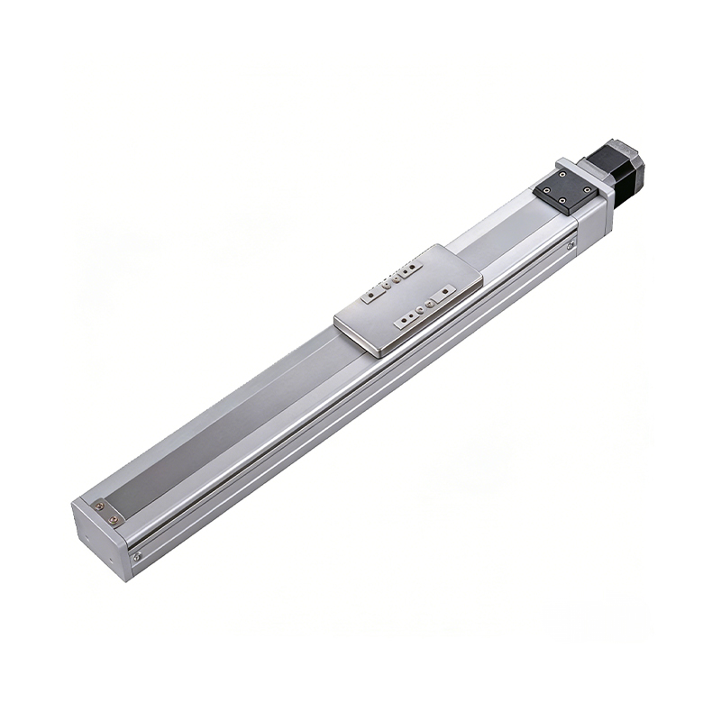 0.01mm High Precision Ball Screw Driven Rail-Embedded Linear Module
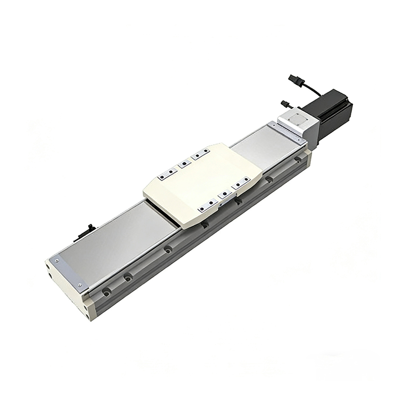 Heavy Load Ball Screw Driven Rail-Embedded Linear Module
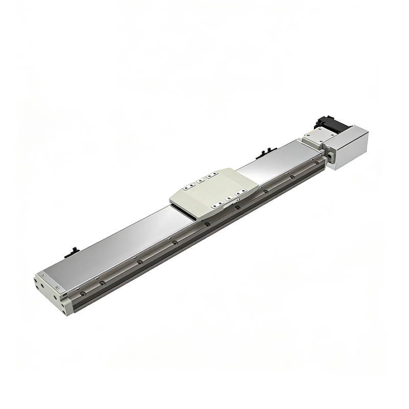 110KG Load Long Stroke Rail-Embedded Linear Module
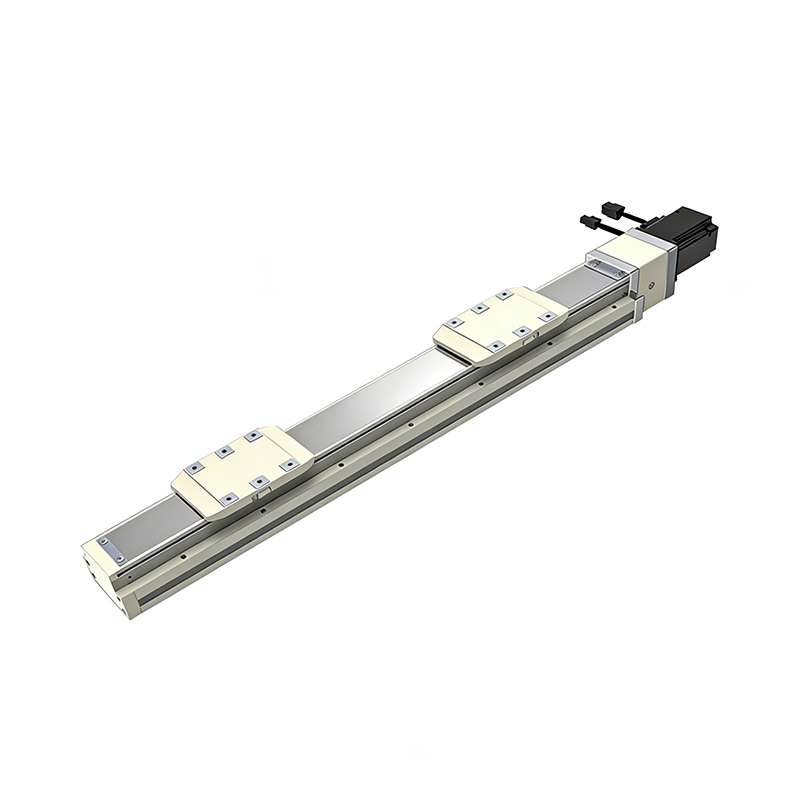 Dual-Slider High Precision Rail-Embedded Linear Module
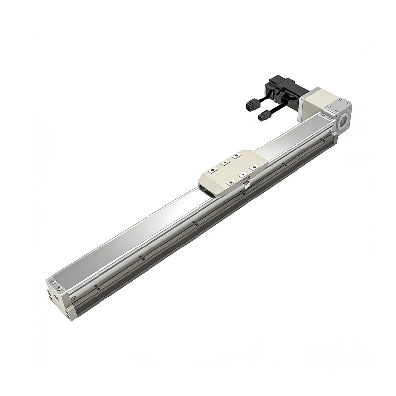 Belt Driven Dust-Proof Rail-Embedded Linear Module
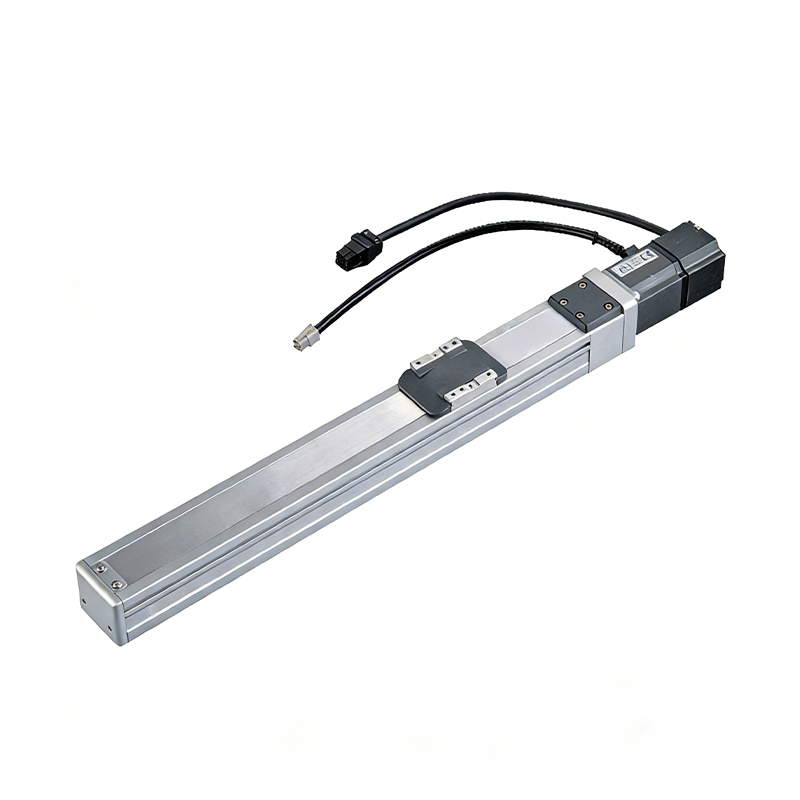 0.01mm High Precision Light Load Ball Screw Linear Module
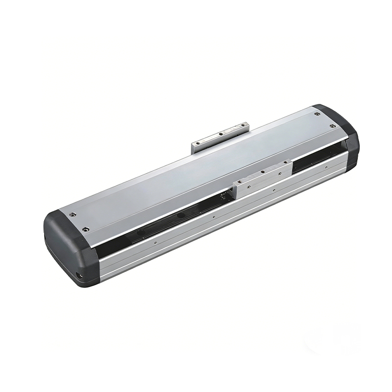 Ball Screw Linear Module with Built-in Sensor
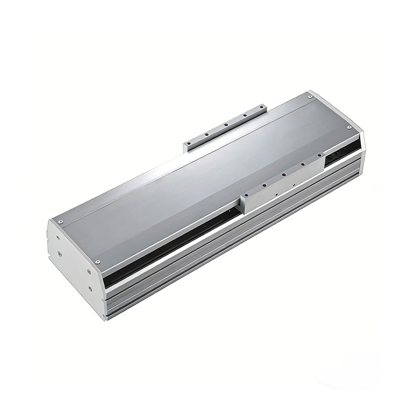 2000mm Long Stroke Ball Screw Linear Module
This 2000mm Long Stroke Ball Screw Linear Module is customized for large-range linear movement automation tasks, support...
READ MOREThis 2000mm Long Stroke Ball Screw Linear Module is customized for large-range linear movement automation tasks, support...
READ MOREThis 2000mm Long Stroke Ball Screw Linear Module is customized for large-range linear movement automation tasks, support...
READ MOREThis 2000mm Long Stroke Ball Screw Linear Module is customized for large-range linear movement automation tasks, support...
READ MORE
If you are interested in our products, please leave us a message. We look forward to providing you with
professional services!
Innovation and transcendence make factory intelligent manufacturing efficient and convenient!
+86 186 2508 0683
19962977901
sales@sz-tys.com
Building 5, Suzhou Mudu International Science and Technology Innovation Park, Jinfeng South Road, Suzhou City, Jiangsu Province, China
