


 English
 Français
 русский
 عربى
 Español
 Deutsch
Tel
+86 186 2508 0683

A pallet-transfer axis is specified with a 300 mm stroke electric cylinder rated at 500 N, installed on a horizontal conveyor line, and commissioned without incident. Eight months later the nut is audible, the axis has lost roughly 0.3 mm of repeatability, and maintenance wants to know why a unit rated nearly three times the measured load failed. The answer is rarely the thrust figure. It is the acceleration peak nobody wrote down, the duty cycle that turned out to be 70 percent instead of 30 percent, the screw running above its critical speed, or a side load introduced by a misaligned bracket.
Sizing electric linear actuators for industrial automation is a sequence of six checks, and they should be run in a fixed order: move profile, thrust, transmission and speed limits, stroke and geometry, duty cycle and thermal margin, then life and precision. When those six are done properly, the catalog selection becomes almost mechanical. When one is skipped, the actuator is chosen on a single number and the consequences surface months later in the field.
The order matters because each check constrains the next. A speed requirement can eliminate a lead screw before thrust is ever discussed. A stroke requirement can force a telescopic design that changes the stiffness calculation. A duty cycle requirement can double the frame size. Working backwards from a catalog page is the most common route to an undersized axis.
The requirement sheet should be finished before any product family is opened. In practice, most sizing errors originate on this sheet rather than in the arithmetic — a missing process force, an assumed friction coefficient, or an acceleration that was never specified because the motion controller had not been configured yet.
Collect the following before anything else:
With those numbers, the peak thrust for a single axis follows a standard relationship:
Fpeak = m·a + m·g·sin θ + μ·m·g·cos θ + Fprocess
Three details in that expression decide most outcomes. First, the gravity term disappears on a horizontal axis but dominates on a vertical one; a 100 kg vertical load at 1 g already contributes 981 N before any acceleration is added. Second, friction acts against motion, so on a decelerating vertical axis the friction term flips sign and the required holding force rises. Third, the acceleration term is often the largest single contributor and is usually the one missing from the enquiry. A 40 kg carriage asked to reach 0.6 m/s in 0.15 s demands 4 m/s², which is 160 N of acceleration force on its own — comparable to the entire steady-state load.
Apply a design factor after the calculation, not inside it, so the reasoning stays visible. A factor of 1.5 on thrust is reasonable for smooth horizontal motion; 2.0 to 2.5 is more appropriate for vertical axes, shock-loaded transfers, or applications where the process force can spike during a jam.
Once peak thrust is known, the motor torque follows from the screw lead and the drive efficiency:
T = (F × P) / (2π × η)
where P is the lead in metres per revolution and η is the mechanical efficiency of the transmission. Ball screws typically run at 0.85 to 0.92, trapezoidal lead screws at 0.30 to 0.50 depending on lead angle and lubrication, timing belts at 0.94 to 0.97, and rack-and-pinion drives around 0.90. A 300 N peak load on a 10 mm lead ball screw therefore needs about 0.53 N·m at the screw, before preload drag, seal drag and inertia are added.
Inertia is the part that separates a paper calculation from a working axis. Reflected screw inertia and carriage inertia both have to be accelerated, and the ratio of load inertia to motor inertia sets how well the loop can be tuned. On ball screw axes a ratio below 5:1 is comfortable, 10:1 is workable with a well-matched drive, and beyond 20:1 the axis will either be slow to settle or prone to oscillation. Belt axes are far more forgiving on inertia ratio because the motor spins faster for the same linear speed, but they pay for it with compliance and belt stretch.
Separate peak torque from continuous torque in the motor datasheet. Peak torque is a thermal transient limited by the drive and the winding; continuous torque is limited by heat rejection and is usually 30 to 40 percent of peak for a servo motor without forced cooling. An axis that needs its peak torque for more than a fraction of each cycle is really a continuous-torque problem, and the frame size should be chosen on that basis.
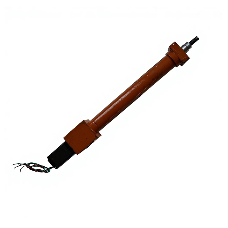 Coaxial Integrated Inline Electric CylinderCompact coaxial motor-and-screw design removes the belt stage, with ±0.01 mm positioning and a 0.25–1000 kN load range for space-limited precision axes.View Product →
Inline electric cylinders keep the motor coaxial with the screw, which produces a compact footprint and removes the belt stage that would otherwise add compliance. For a machine where the actuator sits inside a guard or behind a tooling plate, that geometry often decides the selection as much as the torque figure does.
Transmission choice sets the ceiling on speed, thrust, stiffness and quietness simultaneously, so it is worth comparing the options side by side before committing to a stroke and envelope. The table below summarizes the practical ranges that matter during sizing; individual products will vary, but the trade-offs are consistent across suppliers.
| Transmission | Typical lead or pitch | Practical speed | Continuous thrust range | Repeatability | Best fit | Watch out for |
|---|---|---|---|---|---|---|
| Ball screw | 5–40 mm | 0.3–1.0 m/s | 0.5–20 kN | ±0.01 mm | Precision positioning, pressing, vertical lift | Critical speed, backdriving, cost at long stroke |
| Trapezoidal lead screw | 2–10 mm | 0.05–0.25 m/s | 0.2–5 kN | ±0.05 mm | Self-locking holds, low duty, low cost | Low efficiency, heat, wear at high duty |
| Timing belt | Pulley circumference 40–120 mm | 1.0–3.0 m/s | 0.1–1.5 kN | ±0.1 mm | Long stroke, light load, fast transfer | Belt stretch, tension loss, dust ingress |
| Rack and pinion | Module 1–4 | 1.5–4.0 m/s | 1–10 kN | ±0.05 mm | Very long stroke gantries, machine tools | Lubrication, backlash, rail parallelism |
| Linear motor | Not applicable | 2–10 m/s | 0.2–8 kN | ±0.001 mm | High dynamics, semiconductor, inspection | Cost, magnetic attraction, thermal management |
The table explains why so many mis-specified axes are ball screw units pushed beyond their speed limit. A ball screw is excellent at thrust and precision, mediocre at long stroke and speed, and intolerant of misalignment. If the application needs 2 m/s over 3 m of travel, no amount of thrust margin will rescue a screw design; the correct answer is a belt or rack unit, or a linear motor module with the appropriate magnetic preload.
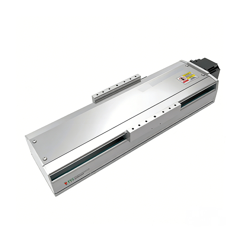 320 kg Heavy-Load Ball Screw Linear ModuleRated for 320 kg with a high-rigidity guide rail and ball screw, suited to heavy material handling where the rail carries moment loads.View Product →
Heavier transfer axes usually settle on a screw-driven module with a sized guide rail, because the rail carries the moment load and the screw only has to produce thrust. Separating those two duties is the reason a module can be rated for hundreds of kilograms while the screw itself is rated for a fraction of that as a bare component.
Three limits cap linear speed, and all three are frequently ignored.
A rotating screw behaves like a shaft in torsion and bending. Above a certain rotational speed, the whirling frequency coincides with the rotation and the screw vibrates violently. The limit scales with diameter and inversely with the square of the unsupported span, and it improves substantially when the screw is supported at both ends rather than fixed at one end and free at the other. A 16 mm screw over a 900 mm span in a fixed-supported arrangement typically begins to be limited in the low thousands of rpm, while a 25 mm screw over the same span tolerates considerably more.
Translate that into linear terms before selecting. With a 10 mm lead, 0.6 m/s requires 3,600 rpm; that is likely beyond a small screw at that span, so the correct response is to move to a 20 mm lead — halving the rpm for the same speed — or to increase the screw diameter. The common failure mode is to specify a fine lead for resolution and then discover the axis cannot reach the required cycle time.
On a horizontal axis, a screw under compression can buckle. The risk grows with stroke and with thrust, and it is the reason long-stroke screw actuators either use a larger diameter screw or switch to a belt or rack. Telescopic cylinders solve the same geometry problem differently: multiple nested tubes collapse to a short retracted length and extend to several times that, at the cost of additional stages, more interfaces, and slightly lower stiffness.
Servo motors deliver constant torque up to base speed and constant power beyond it. If the sizing calculation has been done at stall torque and the real duty point is above base speed, the available torque may be half of what the datasheet promised at zero speed. Stepper motors behave worse still: torque falls steeply with speed, and without an encoder there is no way to know that a stall has occurred. For any axis where the move profile spends meaningful time at high velocity, plot the required torque against speed and overlay the motor curve before ordering.
Acceleration time also has a lower bound that is not purely mechanical. A servo axis needs a few milliseconds to settle after the commanded move, and that settling time depends on stiffness, inertia ratio and encoder resolution. An axis asked to move in 0.1 s with 0.05 s of settling is really a 0.15 s axis, and the cycle rate should be calculated accordingly.
Stroke is not a standalone number. Every actuator converts stroke into envelope, and the conversion ratio varies widely by family. An inline cylinder with a 300 mm stroke may be 600 mm long retracted once the motor, gearbox and rear bearing housing are counted. A foldback design bends the motor alongside the body, shortening the overall length significantly at the expense of width. A four-stage telescopic cylinder might deliver 800 mm of stroke from 280 mm retracted, which is the only way to fit a long lift inside an existing machine frame.
Sketch the retracted and extended envelope for every axis before confirming the order. The most expensive sizing mistake is not a torque error; it is an actuator that fits the load calculation perfectly and does not fit the machine.
Mounting conditions carry their own tolerances. A screw-driven cylinder expects the rod end to travel parallel to the load path within roughly 0.02 to 0.05 mm over the stroke, depending on the bearing arrangement. Exceeding that introduces a side load into the rod bearing, shortens life, and shows up as noise at the end of stroke. Where the driven member cannot be aligned precisely, a rod-end spherical bearing or a floating joint absorbs the misalignment and is worth the small added compliance.
Overhang matters on modules as well as cylinders. A carriage carrying a 300 mm tool offset converts vertical load into a moment that the guide rails must resist, and the resulting rail load can be several times the payload. Rail spacing and block count are selected on that moment, not on the nominal mass. Similarly, a long-stroke horizontal module with the load at the extreme end deflects more than the same module loaded at the centre, and that deflection changes the effective positioning accuracy even when the encoder reports the commanded position.
Continuous thrust ratings are usually quoted at an ambient of around 25 °C with the actuator mounted to a heatsink-like structure and running at a specified duty. Change any of those assumptions and the usable continuous rating drops.
The right way to handle an intermittent cycle is to compute the root-mean-square thrust rather than the average:
Frms = [(F12t1 + F22t2 + … ) / (t1 + t2 + …)]1/2
Squaring the force terms is what makes this calculation different from a simple average, and it matters because heating scales with force squared. An axis that spends 20 percent of its cycle at 900 N and 80 percent at 200 N has an RMS close to 447 N, not 340 N. Selecting on the average will undersize the motor by a comfortable margin.
Ambient temperature then applies a derating. An actuator rated for continuous operation at 25 °C will typically lose 15 to 25 percent of usable thrust at 40 °C and considerably more at 50 °C, because the motor's allowable temperature rise is partly consumed by the environment. Enclosed cabinets, gantries under machine covers, and axes near ovens or welding stations all belong in the higher ambient bracket. Conversely, cold environments bring their own problems: standard grease stiffens below roughly −10 °C, and a wide-temperature or low-temperature lubrication variant is the correct choice rather than a larger motor.
Duty cycle also drives the choice between a servo and an induction or stepper solution. Servo motors tolerate high intermittent overload well but are still thermally limited over a full shift. For an axis that genuinely runs 100 percent duty at high thrust, the honest answer is a larger frame size or a different transmission, not a higher peak current setting.
Life is quoted in kilometres of travel, in revolutions, or in hours, and the three are only interchangeable once lead and cycle time are known. For ball screws and bearings, the basic rating life relationship is:
L10 = (C / P)3 × 10⁶ revolutions
where C is the dynamic load rating and P is the equivalent load. Because the exponent is three, small changes in load produce large changes in life. Doubling the load cuts life by a factor of eight, which is exactly why the RMS calculation in the previous section is worth the effort.
A worked figure makes the sensitivity obvious. With a dynamic rating of 6 kN and an equivalent load of 800 N, the ratio is 7.5, the cube is roughly 422, and the resulting life is about 422 million revolutions. On a 10 mm lead that is 4,220 km of travel — roughly 3.8 million moves of 1.1 m each, or several years of three-shift operation. Halve the load and life roughly octuples; double it and life collapses. This is the arithmetic that separates a ten-year axis from an eighteen-month one.
Belts have a different failure mode. Their life is governed by tooth wear, tension decay and pulley fatigue rather than by rolling contact, and the practical limit is usually stated as a number of flex cycles or a recommended re-tension interval. Rack-and-pinion systems wear at the tooth flank and depend heavily on lubrication quality. In all three cases, the environment — abrasive dust, washdown chemicals, high temperature — can dominate the theoretical life calculation, so a conservative margin is more useful than a precise one.
Finally, distinguish rated life from service life. Rated life assumes correct lubrication, alignment within tolerance, and loads within the stated envelope. A single period of misalignment during commissioning can consume a large share of the theoretical life in a few weeks, which is why alignment records belong in the machine documentation.
These four terms are frequently used interchangeably in enquiries and mean entirely different things.
For a positioning axis, repeatability and backlash usually matter more than absolute accuracy, because accuracy can be compensated in the controller while backlash cannot be removed without a mechanical change. A standard ball nut may show 0.05 mm of axial play; a preloaded nut reduces that below 0.02 mm, and a double-nut preloaded design goes lower still at the cost of drag torque and heat.
Stiffness is a series chain, and the softest element governs. Screw axial stiffness, nut stiffness, bearing support stiffness, coupling torsional stiffness and frame stiffness all add in reciprocal. A rigid screw bolted to a flexible aluminium bracket behaves like a flexible axis. In pressing applications this matters directly: if the target is a force-controlled press fit, the deflection of the load cell, tooling and frame will consume part of the commanded stroke, and the force-displacement curve will not match the bench test.
Feedback resolution sets a floor as well. A 0.01 mm encoder resolution does not deliver 0.01 mm positioning if the loop is detuned to avoid oscillation; in practice the achievable bandwidth is limited by the mechanical resonance, which in turn depends on the moving mass and the stiffness chain described above.
Ingress protection is the specification that is most often copied from a previous project without checking. IP65 protects against dust and low-pressure water jets and is a sensible default for general machine environments. IP68 implies continuous submersion at a stated depth and duration, and should only be specified when the application genuinely requires it, because seals add drag and cost.
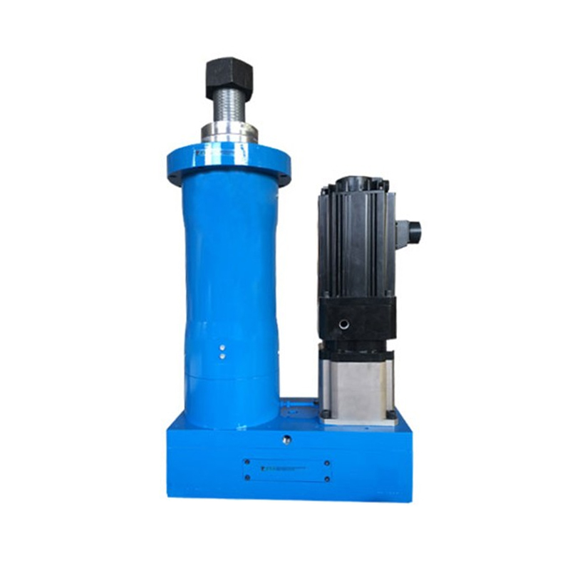 IP65 Splash-Proof Waterproof Electric CylinderSealed aluminum-alloy cylinder with IP65 dust and splash protection, offering up to 200 kN rated force for harsh outdoor and washdown-adjacent applications.View Product →
Washdown food and beverage lines, outdoor gantries and coolant-heavy machining cells are the usual candidates for a sealed cylinder. Beyond water, three other environmental categories deserve early attention: hazardous areas requiring explosion-proof construction with the appropriate certification, high-temperature zones where heat dissipation and bearing grease choice dominate, and low-temperature zones where standard lubricants become the limiting factor before the motor does.
Dust is a separate problem from water. Abrasive dust entering a ball nut accelerates wear dramatically, and a bellows, a scraper seal or a fully enclosed module is the appropriate response. Because the enclosure also traps heat, a sealed axis often needs a larger frame size than an open one carrying the same load — a detail that is easy to miss when the enclosure is chosen after the actuator.
The actuator is only half the axis. The motor and drive determine whether the calculated thrust is actually achievable at the required speed and how well the axis behaves at the end of the move.
Servo motors with absolute encoders remove homing routines and hold position through power cycles, which matters on multi-axis machines where re-referencing costs cycle time. They also allow torque limiting, which is the standard way to protect a press-fit or clamping axis from overforce. Stepper-based actuators are cheaper and adequate for light, slow, non-critical indexing, provided the acceleration is kept well below the pull-out curve and the axis is not expected to detect a stall. Closed-loop steppers sit between the two and offer stall detection at modest cost.
Check the supply and the drive together. A 48 VDC actuator cannot be driven from a 24 V rail without losing speed and thrust, and a 220 VAC servo drive has different cabling, EMC and cabinet space requirements than a DC unit. Communication protocol matters too: EtherCAT, PROFINET, Modbus and pulse-direction control impose different cycle times and different levels of diagnostic detail, and retrofitting a bus interface after delivery is rarely cheap.
Brakes deserve a specific mention. A spring-applied, power-released holding brake is not a dynamic brake and should not be used to stop a moving load; it holds position after the drive has stopped. On vertical axes, the brake plus a counterbalance or a self-locking transmission is the standard combination, and the brake should be rated for at least the static load with margin.
Vertical motion concentrates risk. A ball screw with a lead angle above roughly 5 degrees will backdrive under load, so a loss of power lets the carriage fall unless a brake or counterbalance is present. Trapezoidal lead screws in the same geometry are often self-locking, which is why they persist in low-duty lift applications despite their poor efficiency.
Size the vertical axis for the static load plus acceleration in both directions, then add a separate check for the emergency-stop case. A servo drive that disables on fault produces a sudden loss of torque; the mechanical system must either hold the load or bring it down in a controlled way. Regenerative energy during a descending move also has to go somewhere, and a drive without a brake resistor or shared DC bus may trip on overvoltage during a fast descent.
For a vertical axis carrying a person-adjacent load, the sizing calculation should be reviewed against the applicable machinery safety standard, and the brake should be monitored rather than assumed to be engaged. Even in less critical applications, a brake wear check belongs in the preventive maintenance schedule.
Putting the six checks into a fixed order produces a defensible selection. The sequence below is the one that works most reliably on industrial projects.
The worked example below applies those steps to a representative horizontal transfer axis. The numbers are illustrative, but the structure is the same one used on real projects.
| Parameter | Value | Effect on selection |
|---|---|---|
| Moving mass | 40 kg | Sets acceleration force and inertia ratio |
| Orientation | Horizontal | No gravity term; friction only |
| Friction coefficient | 0.05 (profile rail) | Contributes about 20 N |
| Process force | 100 N | Added to every phase |
| Peak velocity | 0.6 m/s | Drives lead and rpm choice |
| Acceleration time | 0.15 s | 4 m/s², about 160 N acceleration force |
| Peak thrust | ≈ 300 N | Before a 1.5 design factor |
| Lead and speed check | 10 mm lead needs 3,600 rpm | Above critical speed at 900 mm span; move to 20 mm lead at 1,800 rpm |
| Motor torque | ≈ 0.53 N·m at 10 mm lead | Roughly 0.27 N·m with the 20 mm lead, before inertia |
| RMS thrust | ≈ 175 N | Continuous rating must exceed this at 40 °C ambient |
| Life check | 6 kN rating, 800 N equivalent load | ≈ 422 million revolutions, comfortably above target |
Notice how the selection changed at step five. The 10 mm lead satisfied the torque requirement with room to spare but could not deliver the speed, so the lead doubled and the torque requirement halved. That is the normal shape of a sizing exercise: the binding constraint is rarely the one the enquiry was written around.
Most of the failures seen in the field trace back to a short list of errors, and each has a straightforward countermeasure.
Procurement risk also lives in the interface between suppliers. When the actuator, the guide rail, the coupling and the machine frame come from four different vendors, none of them owns the alignment tolerance. Writing that tolerance into the purchase specification, and recording the measured alignment at commissioning, removes most of the ambiguity later. It is worth confirming the supplier's testing regime as well — whether each unit is run-in and functionally tested, and whether the test record travels with the unit.
For engineers working across several machine types, it helps to keep a reusable sizing sheet that captures the ten inputs from the first section and calculates thrust, torque, RMS load and life automatically. Once the sheet exists, the marginal cost of evaluating a second or third transmission option drops to minutes, and the comparison usually reveals that the first instinct was not the best fit. Suppliers who build both cylinders and modules — and who can discuss how the two behave on mechanical automation projects — are often the fastest route to that comparison.
Sizing an electric linear actuator for industrial automation comes down to treating the axis as a system rather than a component. The move profile defines the load, the load defines the torque, the torque and the speed together define the transmission, and the duty cycle plus the environment decide how much of the catalog rating is actually available. Precision requirements then sit on top of that as a separate filter, because an axis can be strong enough and fast enough and still be wrong for a process that needs 0.01 mm of repeatability.
The practical discipline is to write the numbers down in a fixed order and keep the assumptions visible. A sizing sheet that shows a 300 N peak, a 175 N RMS, a 1,800 rpm duty point and a calculated life of 400 million revolutions is auditable. A selection made by scanning a catalog page for a thrust figure that looks comfortably large is not, and the gap between the two tends to appear about eight months after commissioning.
Start with the move, verify the speed limit before the torque, and check the duty cycle before the peak. Those three habits prevent the majority of the failures that get diagnosed, eventually, as an actuator that was "rated for the load."
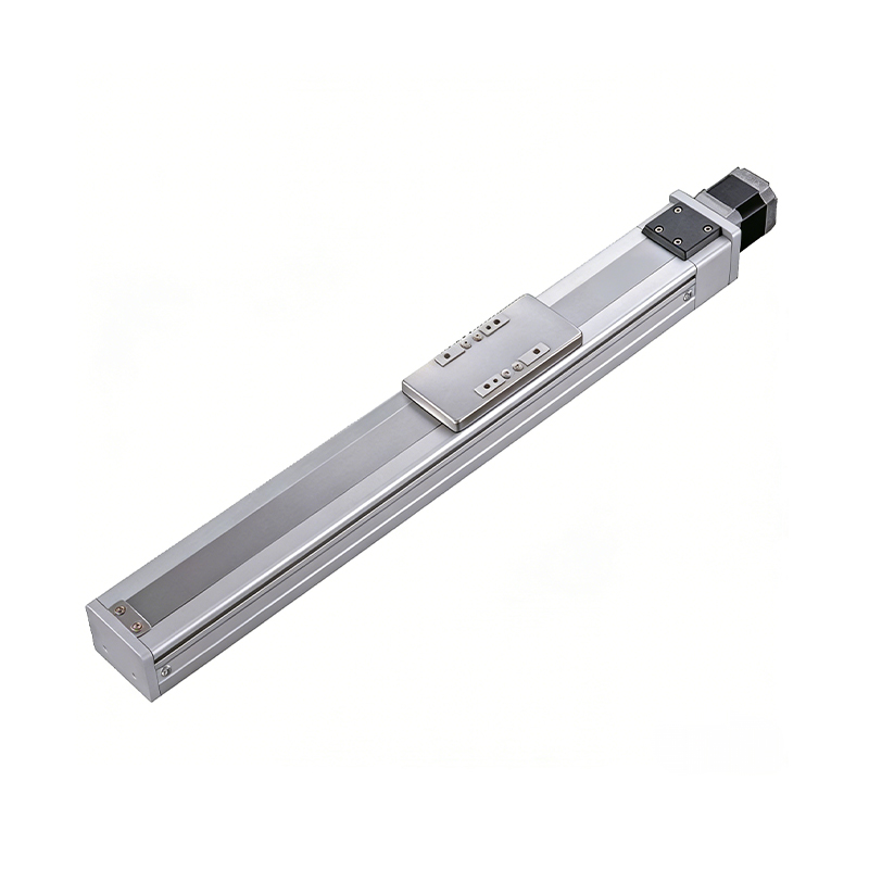 0.01mm High Precision Ball Screw Driven Rail-Embedded Linear Module
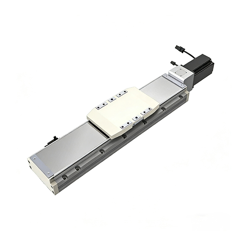 Heavy Load Ball Screw Driven Rail-Embedded Linear Module
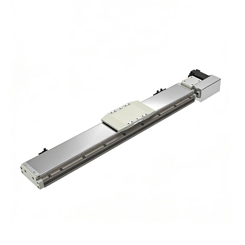 110KG Load Long Stroke Rail-Embedded Linear Module
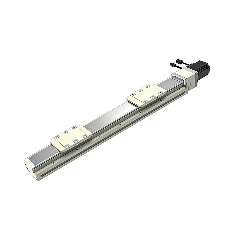 Dual-Slider High Precision Rail-Embedded Linear Module
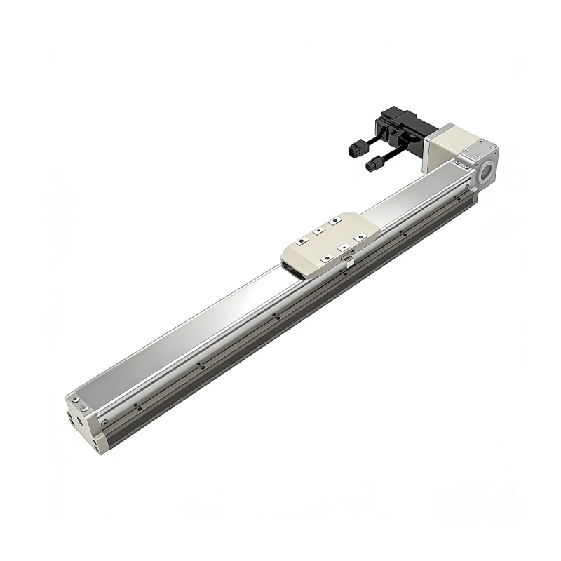 Belt Driven Dust-Proof Rail-Embedded Linear Module
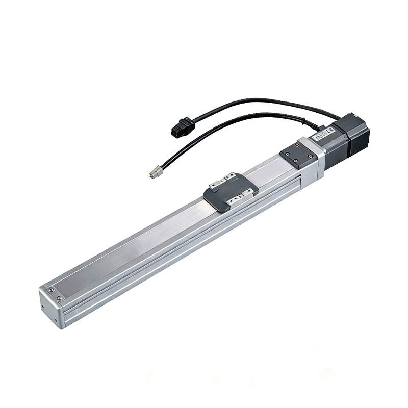 0.01mm High Precision Light Load Ball Screw Linear Module
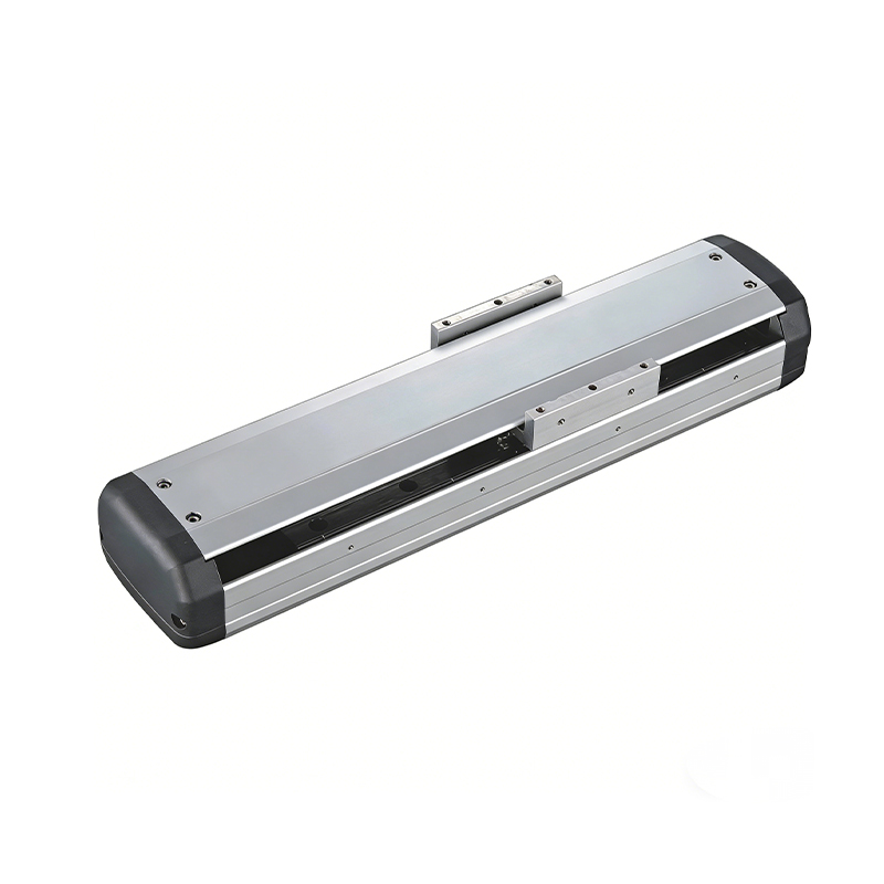 Ball Screw Linear Module with Built-in Sensor
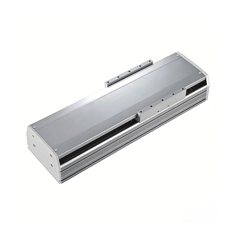 2000mm Long Stroke Ball Screw Linear Module
This 2000mm Long Stroke Ball Screw Linear Module is customized for large-range linear movement automation tasks, support...
READ MOREThis 2000mm Long Stroke Ball Screw Linear Module is customized for large-range linear movement automation tasks, support...
READ MOREThis 2000mm Long Stroke Ball Screw Linear Module is customized for large-range linear movement automation tasks, support...
READ MOREThis 2000mm Long Stroke Ball Screw Linear Module is customized for large-range linear movement automation tasks, support...
READ MORE
If you are interested in our products, please leave us a message. We look forward to providing you with
professional services!
Innovation and transcendence make factory intelligent manufacturing efficient and convenient!
+86 186 2508 0683
19962977901
sales@sz-tys.com
Building 5, Suzhou Mudu International Science and Technology Innovation Park, Jinfeng South Road, Suzhou City, Jiangsu Province, China
