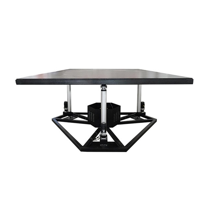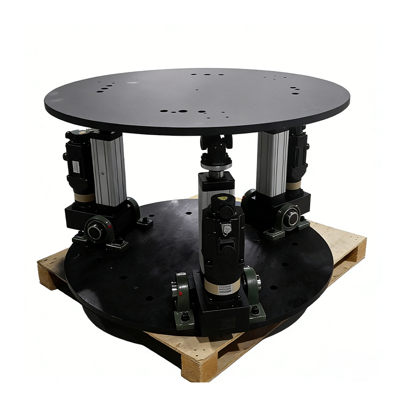
Three-Degree-of-Freedom Platform Custom

Home / Products / Multi-Degree of Freedom Platform / Three-Degree-of-Freedom Platform

About Us
Suzhou Tongyousheng Electronic Technology Co., Ltd.

Suzhou Tongyousheng Electronic Technology Co., Ltd. is a leading high-tech enterprise integrating R&D, production and sales, specializing in the design, manufacturing and distribution of premium automation equipment and components—including electric cylinders, linear slide modules, linear motor modules, servo presses, robotic 7th axes, and six-degree-of-freedom platforms.

As China Three-Degree-of-Freedom Platform Manufacturers and Three-Degree-of-Freedom Platform Suppliers, we recognize technological innovation as the cornerstone of sustainable growth. Our R&D team, composed of industry veterans with deep technical expertise and extensive hands-on experience, serves as the engine driving our continuous progress. By pushing technical boundaries, accelerating product iteration, and pioneering industry advancements, we have secured a portfolio of core patents that underscore our leadership in automation and deliver a decisive competitive edge. We further reinforce our capabilities with state-of-the-art R&D tools, professional design software, and high-precision CNC machining centers, ensuring every development effort is backed by world-class resources.

Through years of relentless exploration and execution, Tongyousheng has established itself as an industry benchmark, renowned for its robust R&D, cutting-edge products, and uncompromising quality. We are dedicated to advancing the Industry 4.0 revolution, collaborating with state-owned enterprises, defense technology institutions, and top-tier universities to build a deeply integrated ecosystem of industry, academia, and research—pushing the frontiers of intelligent manufacturing together. At the heart of our mission is a commitment to delivering automation solutions that are intuitive to operate, highly efficient, ultra-reliable, and cost-effective. Every product we create is a reflection of our technical ingenuity and a direct response to our customers' evolving needs.
Certificate Of Honor
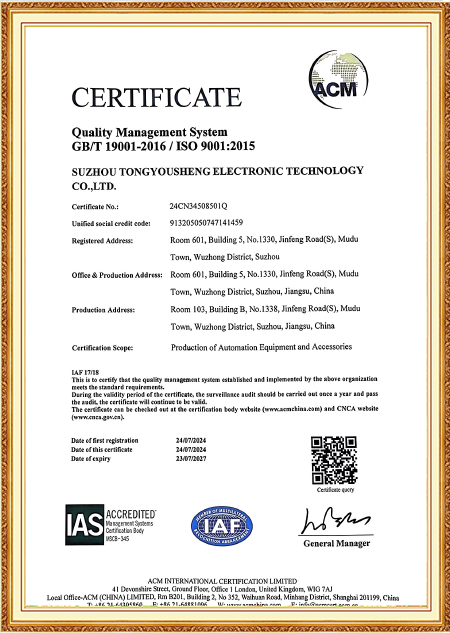
  • ISO 9001:2015 Certificate
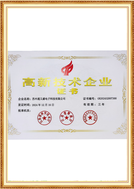
  • High-tech Enterprise Certificate
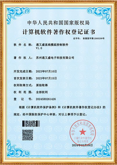
  • Copyright Certificate
  • Copyright Certificate
  • Software Copyright Certificate
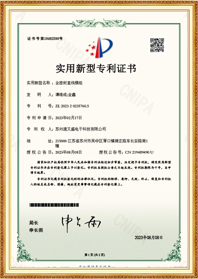
  • Patent Certificate
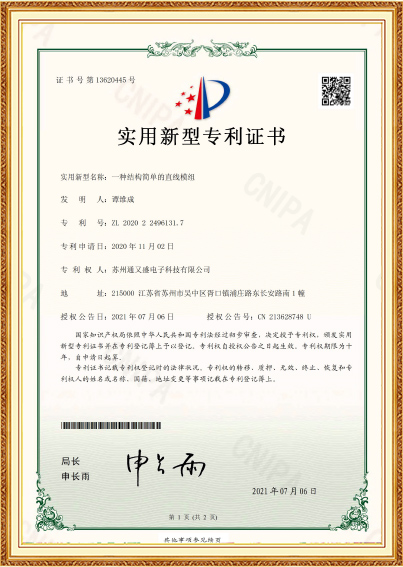
  • Patent Certificate
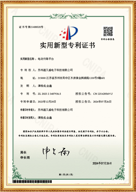
  • Patent Certificate
Message Feedback
Blog
Three-Degree-of-Freedom Platform Industry knowledge

Kinematic Modeling and Axis Coordination Behind a Three-Degree-of-Freedom Platform

The Gap Between a Working Prototype and a Platform That Holds Its Line

A three-degree-of-freedom platform can move through pitch, roll, and yaw on a test bench without much trouble — the real question surfaces once all three axes are commanded to move together toward a specific attitude rather than one at a time. At that point, whether the underlying kinematic model was built correctly stops being an abstract math exercise and starts showing up as either a clean convergence to the target orientation or a small residual error that never quite settles. This distinction is where a supplier's depth in parallel-structure kinematics separates itself from a team that simply assembled a mechanism and tuned the control loop by trial and error afterward.

What Kinematic Modeling Actually Has to Solve

For a parallel mechanism such as a Stewart-type or hexapod-derived three-axis platform, the inverse kinematics problem — converting a desired pitch/roll/yaw command into individual actuator lengths or joint angles — involves solving a set of coupled nonlinear equations rather than independent axis calculations. If the model used during development approximates this relationship with simplified linear assumptions valid only near the neutral position, the platform will track commands accurately close to center but drift measurably as it approaches the edges of its working envelope. Suzhou Tongyousheng Electronic Technology Co., Ltd. builds this consideration into how platform control firmware gets validated, since a model that only gets checked at small angles tends to hide its weaknesses until a customer's application pushes the platform toward its full range.

Where This Shows Up in Actual Control Behavior

A platform running on an under-modeled kinematic chain typically exhibits a specific symptom: commanded roll produces a small unintended yaw component, or a pure pitch command introduces a slight lateral shift at the payload mounting point. This cross-axis leakage is rarely visible when testing one axis in isolation, which is why isolated single-axis verification during acceptance testing can miss it entirely. Catching this requires commanding compound attitude changes — pitch and roll together, for instance — and measuring the actual resulting orientation against the commanded one across multiple points in the workspace, not just at the platform's home position.

Single-axis calibration only Confirms each actuator moves correctly but does not reveal coupling errors that only appear during compound motion
Full-envelope kinematic validation Requires measuring compound pitch-roll-yaw commands at multiple workspace points, not just near center
Linear approximation near neutral Adequate for small-angle applications but breaks down as the platform approaches its working envelope limits
Full nonlinear inverse kinematics Adds computational load to the controller but keeps tracking accuracy consistent across the full range of motion

Getting the Axes to Sit Where the Drawing Says They Should

Before any of this control-side work matters, the physical assembly has to place the platform's rotational axes in the spatial relationship the kinematic model assumes. For a three-axis platform built around a base plate, a moving plate, and a set of struts or linkages connecting them, this means the pivot points on both plates need to sit at the coordinates specified in the design — not approximately close, since even a small positional error at one joint propagates through the entire kinematic chain and shows up as an attitude error that no amount of software compensation fully removes. Assembly technicians typically use a coordinate measuring machine or a laser tracker to verify joint locations against the nominal design before final tightening, rather than relying on jig fixtures alone to guarantee placement.

Coordinating Multiple Axes During the Build

Where the platform uses universal joints or spherical bearings at each strut connection, the orientation of these joints relative to one another also needs to be checked, since a joint that is positionally correct but rotationally misaligned can still introduce binding or restricted range of motion once the platform is fully assembled and under load. Some assembly sequences build the platform in a partially constrained state first — with struts loosely fitted — sweep the plates through a portion of their intended range to check for interference or binding, and only fully torque the joints once free movement across the range is confirmed. Suzhou Tongyousheng Electronic Technology Co., Ltd. has found that skipping this intermediate check tends to surface as a stiff spot or a slight jerk at a specific attitude range rather than a uniform resistance across the whole workspace, which makes the fault harder to trace after final assembly is complete.

Why These Two Factors Rarely Get Evaluated Together

A buyer comparing platform quotes often treats kinematic software and mechanical assembly as separate line items, but the two are tightly linked in a parallel-structure design — a well-derived kinematic model built on assumed joint coordinates that do not match the physical assembly will produce control errors that look like a software bug even though the root cause sits in the mechanical build. Asking a supplier how joint locations get verified during assembly, alongside how the kinematic model handles the full working envelope rather than just small-angle motion, tends to surface more relevant information than reviewing control specifications and mechanical drawings as unrelated documents.