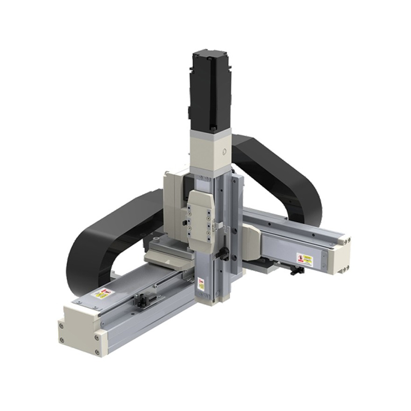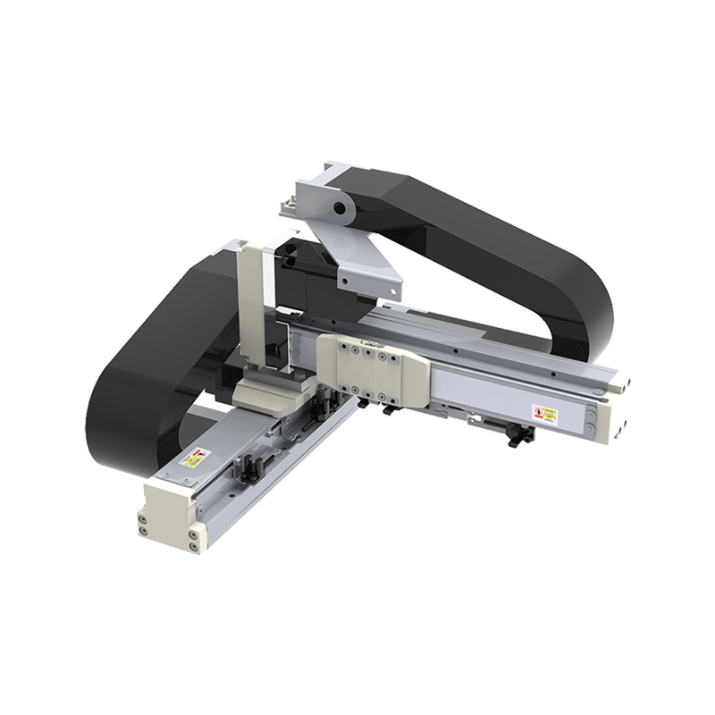
Cartesian Robot Custom

Home / Products / Linear Motion Module / Cartesian Robot

About Us
Suzhou Tongyousheng Electronic Technology Co., Ltd.

Suzhou Tongyousheng Electronic Technology Co., Ltd. is a leading high-tech enterprise integrating R&D, production and sales, specializing in the design, manufacturing and distribution of premium automation equipment and components—including electric cylinders, linear slide modules, linear motor modules, servo presses, robotic 7th axes, and six-degree-of-freedom platforms.

As China Cartesian Robot Manufacturers and Cartesian Robot Suppliers, we recognize technological innovation as the cornerstone of sustainable growth. Our R&D team, composed of industry veterans with deep technical expertise and extensive hands-on experience, serves as the engine driving our continuous progress. By pushing technical boundaries, accelerating product iteration, and pioneering industry advancements, we have secured a portfolio of core patents that underscore our leadership in automation and deliver a decisive competitive edge. We further reinforce our capabilities with state-of-the-art R&D tools, professional design software, and high-precision CNC machining centers, ensuring every development effort is backed by world-class resources.

Through years of relentless exploration and execution, Tongyousheng has established itself as an industry benchmark, renowned for its robust R&D, cutting-edge products, and uncompromising quality. We are dedicated to advancing the Industry 4.0 revolution, collaborating with state-owned enterprises, defense technology institutions, and top-tier universities to build a deeply integrated ecosystem of industry, academia, and research—pushing the frontiers of intelligent manufacturing together. At the heart of our mission is a commitment to delivering automation solutions that are intuitive to operate, highly efficient, ultra-reliable, and cost-effective. Every product we create is a reflection of our technical ingenuity and a direct response to our customers' evolving needs.
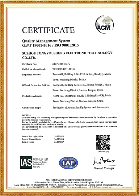

Certificate Of Honor
  • ISO 9001:2015 Certificate
  • High-tech Enterprise Certificate
  • Copyright Certificate
  • Copyright Certificate
  • Software Copyright Certificate
  • Patent Certificate
  • Patent Certificate
  • Patent Certificate
Message Feedback
Blog
Cartesian Robot Industry knowledge

Deflection Control on Cantilevered Axes and the Real Cost Gap Against Articulated Arms

A Palletizing Cell That Started Missing Its Corner Pick Points

A parts-packing line running a three-axis gantry unit began missing pick points at the far corners of its work envelope, specifically when the Z-axis extended near full stroke while carrying a loaded gripper offset from the column centerline. The X and Y axes tracked their commanded positions correctly; the drift concentrated on whichever combination put the heaviest moment arm on the Z-column. This is a familiar failure pattern on any cantilevered cartesian robot configuration — the axis with the longest unsupported reach, carrying the most eccentric load, is where positioning error shows up first, and it rarely surfaces during a light-load commissioning run.

Why an Offset Load Turns Into Positioning Error on a Cantilevered Axis

A cantilevered Z-axis behaves structurally like a beam fixed at one end, and any load applied off the axis centerline generates a bending moment proportional to both load magnitude and offset distance. That moment produces angular deflection at the tool point, and since deflection scales with the cube of unsupported length, a Z-axis extended near full stroke sees a disproportionately larger error than the same load positioned closer to the carriage. The practical fix rarely comes from one measure alone — increasing the cross-sectional stiffness of the Z-column, reducing the moment arm by relocating the load center closer to the guide rail centerline where the fixture allows it, and in some cases adding a secondary support rail that converts a pure cantilever into a partially guided structure.

Larger Z-column cross-section Raises second moment of area, cuts deflection per unit moment applied at the tool point
Reduced load offset through fixture redesign Lowers the bending moment at the base directly, without touching the column itself
Secondary guide rail added to the Z-axis Turns cantilever loading into a partially constrained beam condition

None of these eliminates deflection entirely — a cartesian robot axis carrying an offset load always deflects some measurable amount under load, and the real design question is keeping that deflection inside the tolerance band a given application needs rather than chasing zero. On the packing line, the actual fix turned out to sit in the fixture: relocating the gripper's center of mass closer to the guide rail cut the moment arm enough that the existing column stiffness was already sufficient, without any structural redesign.

Where Simulation Earns Its Keep Before Metal Gets Cut

Predicting deflection analytically gets complicated once the load path involves multiple stacked axes, which is why finite element analysis on the proposed structure — rather than a hand calculation treating the column as a simple cantilever beam — tends to catch interaction effects a simplified model misses, particularly torsional deflection coupling with bending when the load offset isn't purely in one plane. Suzhou Tongyousheng Electronic Technology Co., Ltd. runs structural simulation on custom cartesian robot configurations before committing to a column cross-section, checking deflection at the specific load cases and travel positions the application will actually encounter rather than relying on a generic stiffness figure carried over from a standard catalog frame.

The Cost Comparison That Never Shows Up on a Per-Axis Price Sheet

Comparing a cartesian robot configuration against an articulated arm on price alone misses where the real cost gap opens up. An articulated arm's reach and payload rating are coupled — extending reach on a six-axis arm means every downstream joint carries more moment, which pushes up motor sizing, gearbox cost, and structural mass through the entire kinematic chain. A gantry-style cartesian robot scales differently: extending the X or Y axis mainly adds rail length and structural beam, without forcing every other axis to be re-sized to compensate for a growing moment arm at the base. For an application spanning several meters of travel with a heavy, awkwardly shaped payload — a fairly common profile in panel handling or large-format press-fitting work — that difference compounds quickly.

Cost scaling with travel length Articulated arm costs rise steeply as every joint upsizes with reach; gantry cost stays closer to linear, driven mainly by rail and beam length
Payload at extended reach Arm's rated payload drops as reach increases; gantry payload stays largely independent of travel position

This doesn't make an articulated arm the wrong choice broadly — for compact, multi-orientation tasks within a modest envelope, an arm's flexibility in tool orientation is hard to match with a Cartesian layout. The cost-performance gap favoring a cartesian robot configuration is specific to the combination of long travel and heavy or eccentric payload, where an arm would need progressively larger joints just to hold rated capacity at the far end of its reach, while a gantry axis simply extends its rail without that compounding structural penalty.

What a Buyer Comparing the Two Should Actually Ask

Rather than comparing catalog price per axis, a buyer evaluating a long-travel, heavy-payload application can ask a supplier to quote both configurations at the actual travel distance and payload the process requires, including how payload rating changes across the full stroke rather than just at a nominal test point. For the cartesian robot option specifically, asking whether deflection at the worst-case load position has been verified through simulation or physical testing — rather than assumed from a lighter reference load — tends to separate suppliers who engineered the structure for the actual duty cycle from those quoting a standard frame size against a generic spec sheet.