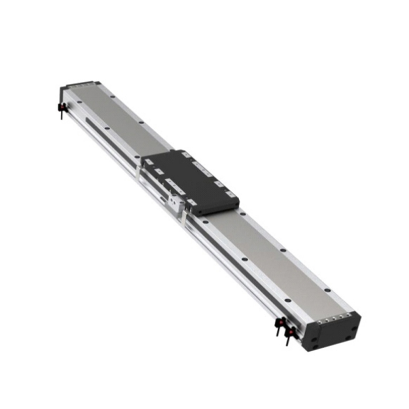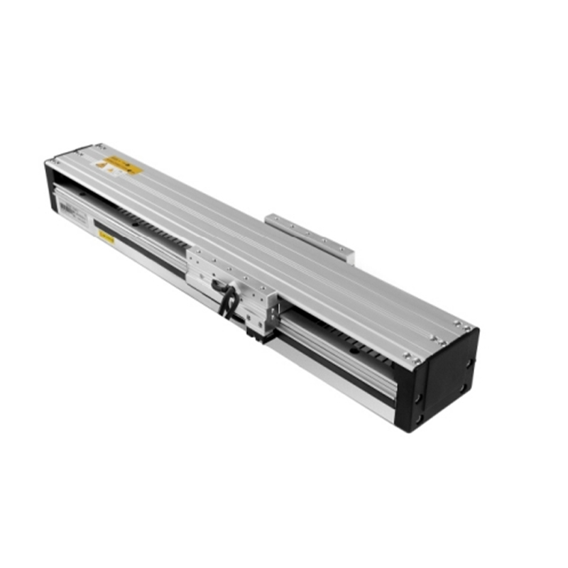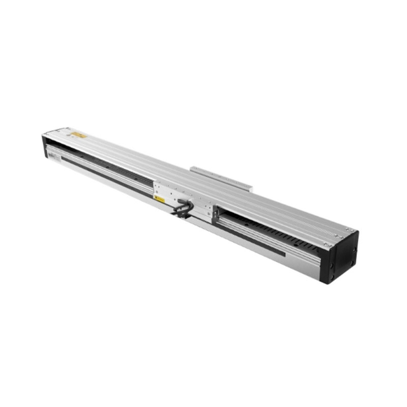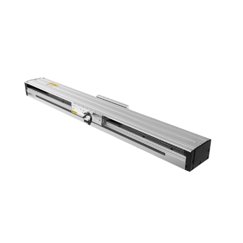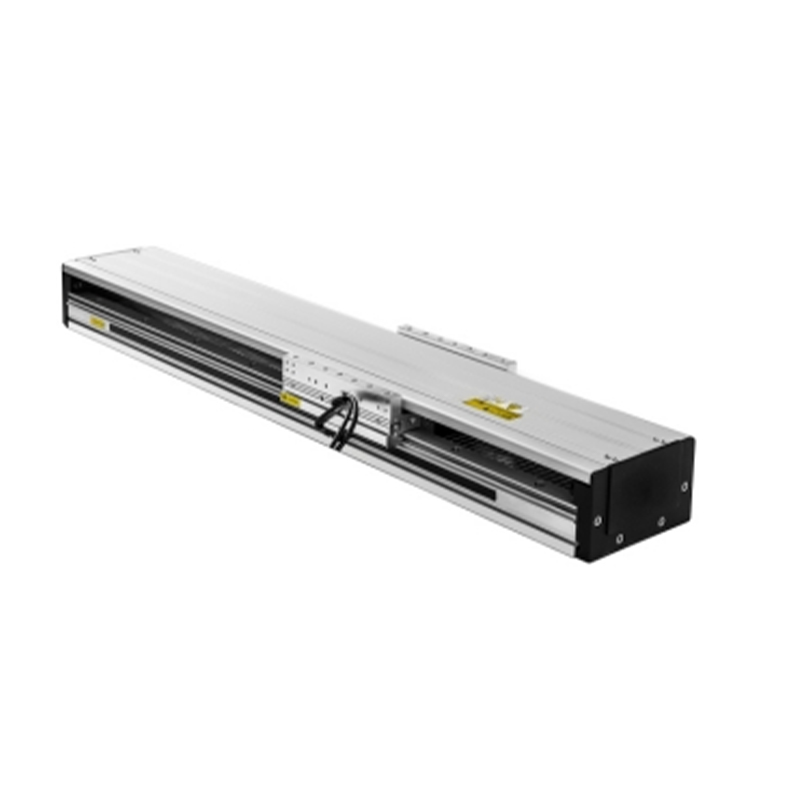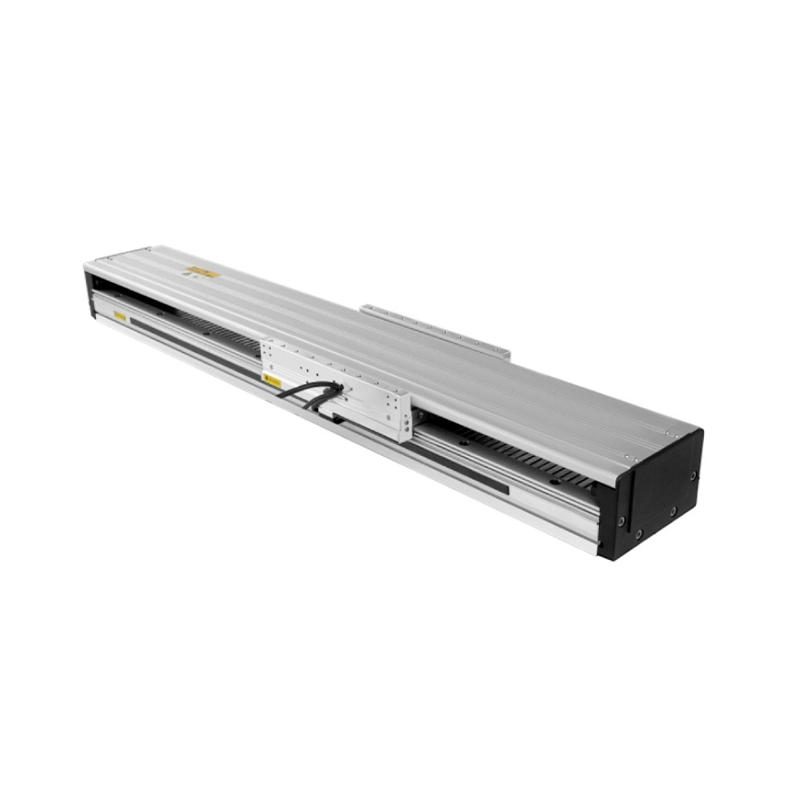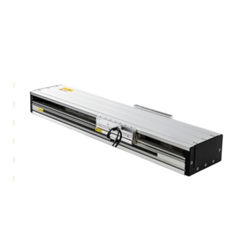
Linear Motor Module OEM/ODM

Home / Products / Linear Motor Module

About Us
Suzhou Tongyousheng Electronic Technology Co., Ltd.

Suzhou Tongyousheng Electronic Technology Co., Ltd. is a leading high-tech enterprise integrating R&D, production and sales, specializing in the design, manufacturing and distribution of premium automation equipment and components—including electric cylinders, linear slide modules, linear motor modules, servo presses, robotic 7th axes, and six-degree-of-freedom platforms.

As China Linear Motor Module Manufacturers and Linear Motor Module Factory, we recognize technological innovation as the cornerstone of sustainable growth. Our R&D team, composed of industry veterans with deep technical expertise and extensive hands-on experience, serves as the engine driving our continuous progress. By pushing technical boundaries, accelerating product iteration, and pioneering industry advancements, we have secured a portfolio of core patents that underscore our leadership in automation and deliver a decisive competitive edge. We further reinforce our capabilities with state-of-the-art R&D tools, professional design software, and high-precision CNC machining centers, ensuring every development effort is backed by world-class resources.

Through years of relentless exploration and execution, Tongyousheng has established itself as an industry benchmark, renowned for its robust R&D, cutting-edge products, and uncompromising quality. We are dedicated to advancing the Industry 4.0 revolution, collaborating with state-owned enterprises, defense technology institutions, and top-tier universities to build a deeply integrated ecosystem of industry, academia, and research—pushing the frontiers of intelligent manufacturing together. At the heart of our mission is a commitment to delivering automation solutions that are intuitive to operate, highly efficient, ultra-reliable, and cost-effective. Every product we create is a reflection of our technical ingenuity and a direct response to our customers' evolving needs.
Certificate Of Honor
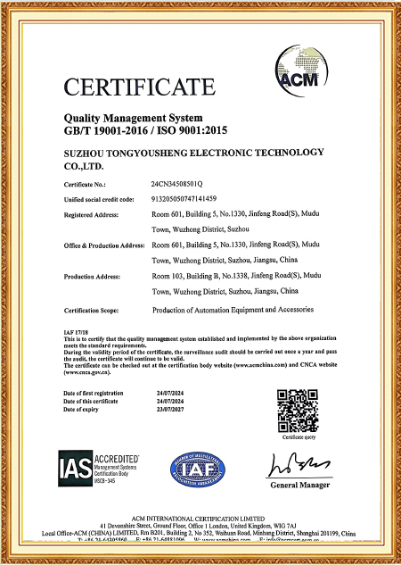
  • ISO 9001:2015 Certificate
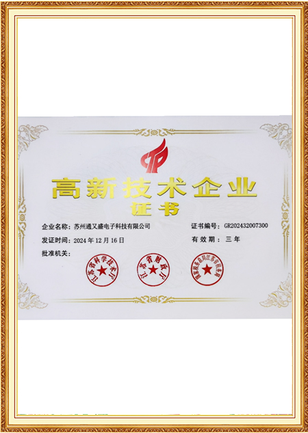
  • High-tech Enterprise Certificate
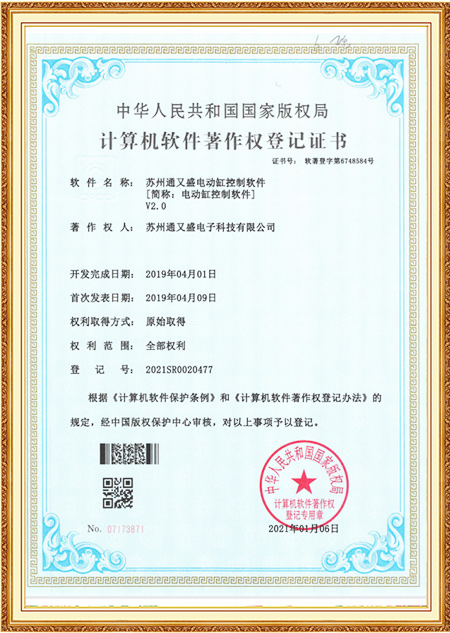
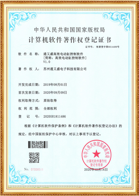
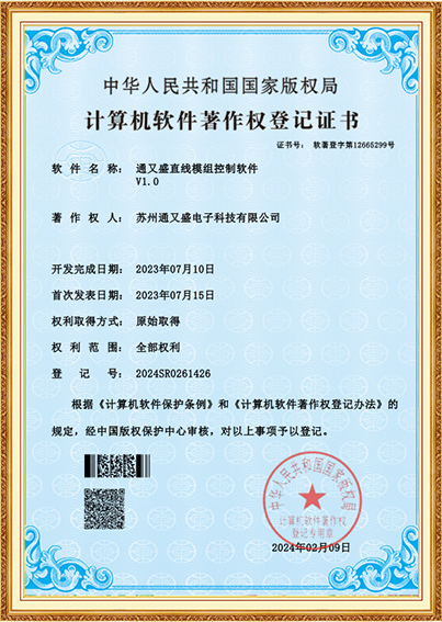
  • Copyright Certificate
  • Copyright Certificate
  • Software Copyright Certificate
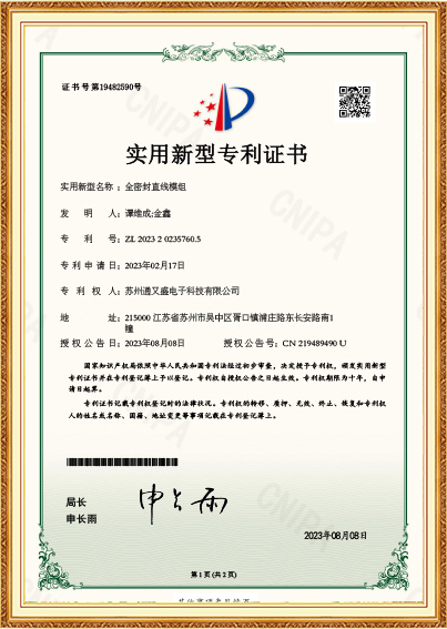
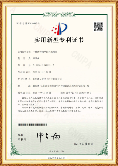
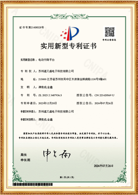
  • Patent Certificate
  • Patent Certificate
  • Patent Certificate
Message Feedback
Blog
Linear Motor Module Industry knowledge

Linear Motor Module: Why Track Joints and Core Type Decide How Smooth an Axis Really Feels

A wafer-handling gantry running at low speed but requiring sub-micron settling had an odd symptom during commissioning: the velocity trace looked clean on the oscilloscope until the axis crossed a specific position on its travel, where a small but repeatable ripple appeared every single pass. It turned out to be a joint between two segments of the magnetic track — the gap at that seam was fractionally wider than the rest of the track, and every time the mover's coil array crossed it, the force output dipped just enough to register as a velocity disturbance. On a long-stroke linear motor module built from multiple track segments, this kind of joint-induced ripple is one of the more difficult problems to diagnose because it only shows up at specific positions rather than uniformly across the stroke.

Why Track Segment Gaps Matter More Than They Look

Magnetic tracks for long-stroke applications are almost never machined as a single continuous piece — they're built from multiple magnet segments bolted or bonded end to end, and the gap at each joint interrupts the otherwise periodic magnetic field the mover's coils are riding on. If that gap is wider or narrower than the segments on either side of it, the field discontinuity at that exact point produces a local thrust dip or spike. The tighter and more consistent this gap tolerance is held across every joint in a track — and across every track in a production batch — the less that joint contributes to overall thrust ripple.

Joint Gap Tolerance Typical Ripple Contribution Application Sensitivity
±0.05mm or looser Noticeable local thrust dip at each joint Acceptable for general transfer axes
±0.02mm Reduced but still measurable disturbance Suitable for moderate-precision positioning
±0.01mm or tighter Minimal, close to background ripple level Needed for settling-sensitive stations

Batch Consistency Is a Separate Question From Single-Unit Quality

A single track segment can pass its own dimensional check and still contribute to a ripple problem if the segment installed next to it during assembly came from a different production run with a slightly different gap habit. This is where batch-level consistency becomes more relevant than any individual segment's spec sheet. Suzhou Tongyousheng Electronic Technology Co., Ltd. controls segment alignment and joint gap during track assembly on a per-order basis rather than treating each segment as an interchangeable stock item, which keeps the cumulative ripple contribution from joints closer to a predictable band across the full length of a long-stroke linear motor module.

Iron-Core Versus Coreless: A Different Kind of Ripple Problem

Separate from joint gaps, the choice between iron-core and coreless motor construction introduces its own smoothness question — cogging force. Iron-core motors use laminated steel teeth to concentrate the magnetic field around the coil windings, which increases thrust density for a given coil size but also creates a periodic attraction between the teeth and the magnet track as the mover travels. This attraction doesn't disappear even with the motor unpowered, and it shows up as a position-dependent force ripple that's hardest to eliminate at low speed, where the servo loop has less momentum to smooth over it.

What Removing the Core Actually Trades Away

Coreless motors remove the iron teeth entirely, which eliminates cogging force as a mechanism since there's no steel structure to attract toward the magnets. The trade-off is thrust density — without iron concentrating the field, a coreless motor typically needs a larger coil winding or more magnet length to produce the same force output, and the coil itself runs at a higher current density for a given thrust, which raises heat generation per unit volume. For applications where motion smoothness at low speed matters more than compact size — scanning stages, optical inspection axes, dispensing heads — this trade generally favors the coreless design despite the larger footprint.

Motor Type Cogging Force Thrust Density Typical Fit
Iron-core Present, position-dependent Higher for given coil size Heavy load, compact envelope
Coreless Negligible Lower, larger coil needed Low-speed precision, scanning

How the Two Issues Compound on a Real Axis

On a station combining a long-stroke track with an iron-core mover, joint ripple and cogging ripple don't necessarily occur at the same frequency, which means they can either partially cancel or reinforce depending on the mover's position relative to a joint at any given moment — something that's difficult to predict analytically and is usually caught during commissioning rather than in the design phase. This is one reason a linear motor module intended for settling-sensitive work benefits from tight joint tolerance even when a coreless motor is already handling the cogging side of the problem, since joint-induced ripple operates independently of core type.

Practical Verification Before Committing to a Design

A buyer evaluating two quotes with similar thrust ratings can ask for a measured thrust ripple curve across a full stroke rather than relying on the nameplate force figure alone — this reveals both the joint-crossing dips and the underlying cogging pattern in one trace. Requesting this curve at the actual operating speed of the target application matters too, since cogging ripple's visibility changes with velocity, and a curve taken at high speed can mask a problem that only appears once the axis slows down for a settling or dwell segment of its cycle.