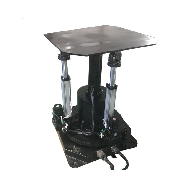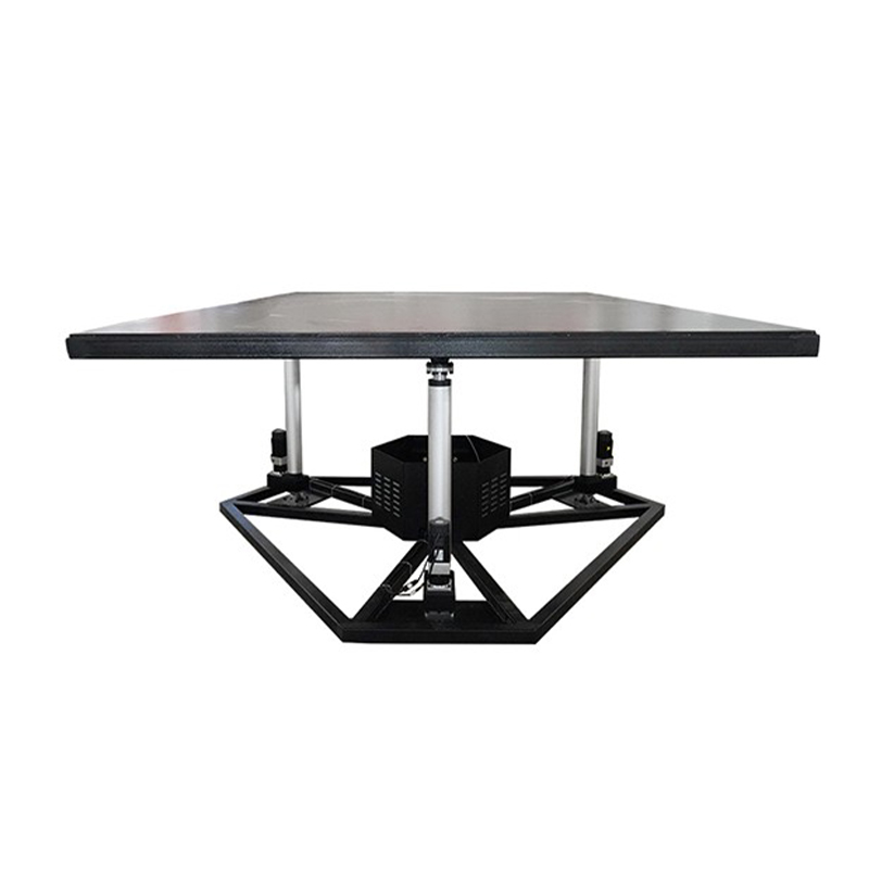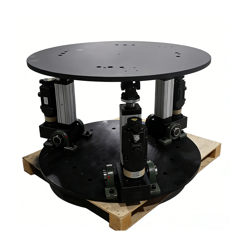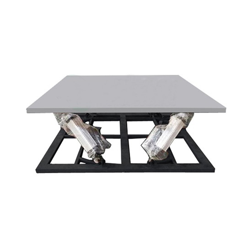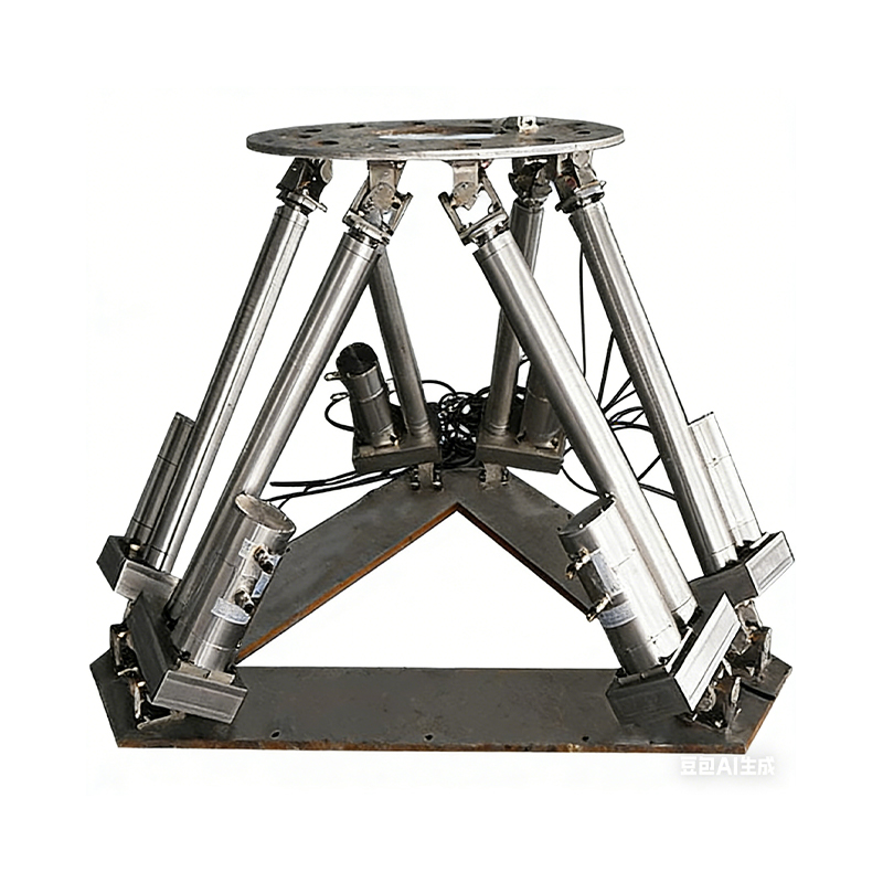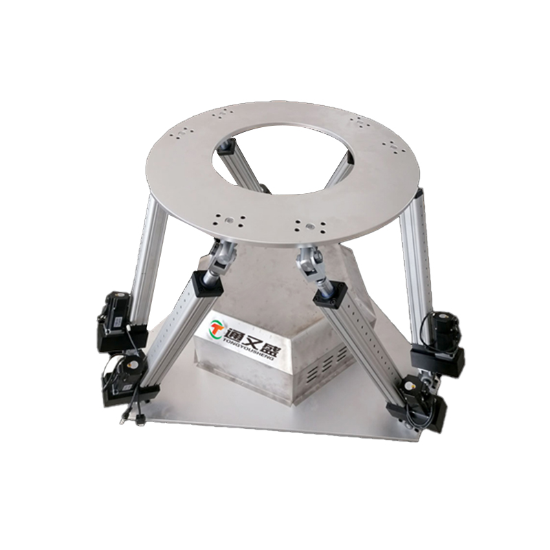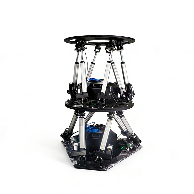
Multi-Degree of Freedom Platform OEM/ODM

Home / Products / Multi-Degree of Freedom Platform

About Us
Suzhou Tongyousheng Electronic Technology Co., Ltd.

Suzhou Tongyousheng Electronic Technology Co., Ltd. is a leading high-tech enterprise integrating R&D, production and sales, specializing in the design, manufacturing and distribution of premium automation equipment and components—including electric cylinders, linear slide modules, linear motor modules, servo presses, robotic 7th axes, and six-degree-of-freedom platforms.

As China Multi-Degree of Freedom Platform Manufacturers and Multi-Degree of Freedom Platform Factory, we recognize technological innovation as the cornerstone of sustainable growth. Our R&D team, composed of industry veterans with deep technical expertise and extensive hands-on experience, serves as the engine driving our continuous progress. By pushing technical boundaries, accelerating product iteration, and pioneering industry advancements, we have secured a portfolio of core patents that underscore our leadership in automation and deliver a decisive competitive edge. We further reinforce our capabilities with state-of-the-art R&D tools, professional design software, and high-precision CNC machining centers, ensuring every development effort is backed by world-class resources.

Through years of relentless exploration and execution, Tongyousheng has established itself as an industry benchmark, renowned for its robust R&D, cutting-edge products, and uncompromising quality. We are dedicated to advancing the Industry 4.0 revolution, collaborating with state-owned enterprises, defense technology institutions, and top-tier universities to build a deeply integrated ecosystem of industry, academia, and research—pushing the frontiers of intelligent manufacturing together. At the heart of our mission is a commitment to delivering automation solutions that are intuitive to operate, highly efficient, ultra-reliable, and cost-effective. Every product we create is a reflection of our technical ingenuity and a direct response to our customers' evolving needs.
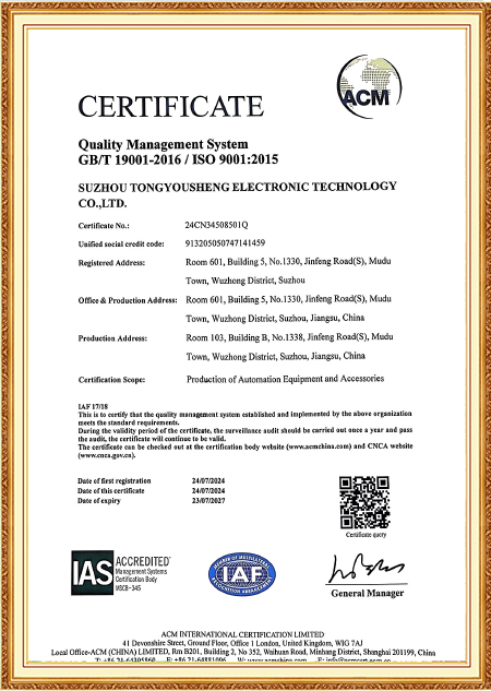

Certificate Of Honor
  • ISO 9001:2015 Certificate
  • High-tech Enterprise Certificate
  • Copyright Certificate
  • Copyright Certificate
  • Software Copyright Certificate
  • Patent Certificate
  • Patent Certificate
  • Patent Certificate
Message Feedback
Blog
Multi-Degree of Freedom Platform Industry knowledge

Load Eccentricity and Plate Calibration: Two Decisions That Shape How a Motion Platform Behaves in Service

During a shaker-table qualification run for an avionics enclosure, the test lab noticed one actuator leg drawing noticeably more current than the rest whenever the platform executed a combined pitch-and-heave sequence. The enclosure itself weighed within spec, but its mounting bracket placed the center of mass close to one edge of the top plate rather than near the middle. Nobody had flagged this during the original order — the request simply listed maximum payload and required travel angles. This kind of gap between how a multidegree-of-freedom-platform gets ordered and how the payload actually sits on it turns up more often than the spec sheet alone would suggest.

Payload Position Changes the Force Picture, Not Just the Total Weight

Rated payload figures on a platform's datasheet generally assume the load's center of mass falls near the geometric center of the mounting surface. Once a bracket, sensor housing, or asymmetric test article shifts that center away from the middle, the actuator legs stop sharing the load evenly. The legs positioned closer to the mass carry a larger portion of both the static weight and, during motion, the inertial force generated as the platform accelerates through its trajectory — meaning two platforms with identical payload ratings can behave very differently in service depending on where that payload's weight is actually concentrated.

Leg Count and Splay Angle as a Response to Eccentricity

A standard six-leg arrangement handles centered, symmetric payloads well with a relatively tight splay angle, since the geometry favors stiffness along the vertical axis under that assumption. Once a known off-center load enters the picture, a wider splay angle or an uneven leg spacing pattern tends to spread that extra force across more of the structure rather than concentrating it on one or two legs working near their duty ceiling while the rest sit underutilized. In some cases, adding a seventh leg or restructuring the base mounting circle addresses an eccentricity problem more directly than adjusting splay angle alone, particularly when the offset is large relative to the plate radius.

Offset From Plate Center Effect on Leg Loading Design Response
Under 10% of plate radius Load spread stays close to even Standard leg layout usually sufficient
10-25% of plate radius Nearest legs carry noticeably more load Wider splay angle or reinforced leg pairing
Over 25% of plate radius Risk of uneven duty cycle wear on specific legs Custom leg count or base geometry redesign

Why This Detail Gets Missed at the Order Stage

Customers ordering a multidegree-of-freedom-platform tend to describe total payload weight, required rotation angles, and frequency range in detail, but the location of the center of mass on the mounting surface often goes unmentioned unless specifically asked. Suzhou Tongyousheng Electronic Technology Co., Ltd. requests a simple load sketch or center-of-mass estimate during the specification review stage for exactly this reason — catching an eccentricity issue before the base and leg geometry are finalized costs far less than redesigning after a prototype has already been built and tested.

Squaring the Plates: A Separate Manufacturing-Floor Question

Apart from how the load sits, there's a question about how the platform itself gets assembled that determines whether its rated pose accuracy actually holds once it leaves the shop floor — specifically, how the upper and lower plates get aligned relative to each other before the leg mounting points are locked down. The kinematic model driving the control software assumes a specific geometric relationship between mounting points on both plates; any gap between that assumed geometry and the physical hardware translates directly into pose error, independent of how well any single actuator performs.

Jig-Based Alignment Versus Measured Calibration

One common assembly method uses fixture jigs and feeler gauges, relying on an assembler's care to square the plates within an acceptable tolerance band before final fastening — a workable approach for platforms with looser accuracy demands. A different method captures the actual measured position of each mounting point on both plates using a laser tracker or portable coordinate measuring arm, then feeds those real coordinates into the kinematic model instead of assuming the hardware matches nominal drawing values exactly. The second method tends to hold tighter pose accuracy because it accounts for the small manufacturing variances that jig-based alignment can't fully capture.

Calibration Approach Dependency on Assembler Skill Typical Application Fit
Jig and gauge alignment Higher, results vary by operator General-purpose motion simulation
Laser tracker or CMM mapping Lower, measurement-driven Sensor calibration rigs, precision test stands

How Eccentric Load and Calibration Method Interact

These two factors don't operate independently in practice, especially when a multidegree-of-freedom-platform is used for precision simulation tasks where payload distribution and geometric accuracy directly influence motion performance. An off-center payload amplifies the visibility of any existing calibration mismatch, because the platform's actual center of rotation drifts slightly from where the control model assumes it sits — and that drift becomes more pronounced under uneven leg loading than it would under a symmetric, centered payload. A platform ordered for a known eccentric-load application often justifies the added cost of measured plate calibration even when the raw accuracy specification alone might not have required it, simply because eccentric loading erodes the margin that would otherwise absorb small calibration errors unnoticed.

What This Means When Comparing Two Otherwise Similar Quotes

A buyer looking at two quotes with matching payload capacity and travel range can ask a supplier directly how leg layout was adjusted for the actual center-of-mass location of their payload, and whether plate calibration was performed against measured coordinates or nominal drawing dimensions. These two details rarely appear on a standard spec sheet, yet they tend to explain more about how a platform performs once installed than the headline payload and accuracy numbers alone.