


 English
 Français
 русский
 عربى
عربى Español
 Deutsch
Tel
+86 186 2508 0683

Motion Control Reference Guide
A practical reference for engineers and buyers who need to understand how electric cylinders work, how they compare to pneumatic and hydraulic options, and how to pick the correct size and configuration.
Direct answer: An electric cylinder is a linear actuator that converts the rotational motion of an electric motor into precise, controllable straight-line movement, typically through a ball screw or lead screw mechanism. It replaces pneumatic or hydraulic cylinders in applications that require accurate positioning, programmable speed, and clean, quiet operation without air compressors or hydraulic fluid.
An electric cylinder looks similar to a pneumatic cylinder from the outside, with a cylindrical or rectangular housing and an extending rod. Inside, the operating principle is completely different. Instead of compressed air or hydraulic oil pushing a piston, an electric motor rotates a screw shaft. A nut riding on that screw is prevented from rotating, so as the screw turns, the nut is forced to move along the shaft in a straight line. That nut is connected to the piston rod, which extends or retracts depending on the direction the motor spins.
Most industrial electric cylinders use one of two screw types:
| Screw Type | Typical Efficiency | Best Suited For |
| Ball screw | 85 to 95 percent | High speed, high duty cycle, precision positioning |
| Lead screw (Acme) | 30 to 65 percent | Lower speed, holding loads without back drive, lower cost |
| Roller screw | 90 percent and above | Very high load and long service life applications |
The motor, screw assembly, and rod are all controlled by a motion controller or a programmable logic controller. This is what makes electric cylinders fundamentally different from pneumatic or hydraulic units. Position, speed, acceleration, and force can all be programmed and adjusted electronically, and the actual position of the rod can be read back through an encoder for closed loop feedback. This means the cylinder can stop at any point along its stroke, not only at the two mechanical end points that a standard pneumatic cylinder is limited to.
Understanding the main components helps when comparing specification sheets between different products.
Motor
Usually a servo motor or stepper motor, mounted in line with the screw or coupled through a belt or gearbox. The motor type largely determines the achievable speed, torque, and positioning resolution.
Screw and Nut Assembly
Converts rotary motion into linear motion. Screw lead, meaning the distance the nut travels per revolution, directly determines the relationship between motor speed and rod speed.
Piston Rod and Guide System
The rod carries the load and is guided by bushings, rails, or an anti-rotation key to keep the rod from spinning while it extends and retracts.
Encoder and Feedback System
Tracks the exact rod position in real time and reports it back to the controller, enabling repeatable, closed loop positioning.
Housing and Seals
Protects internal components from dust, moisture, and debris. Sealing rating is an important factor for cylinders used outdoors or in washdown environments.
Electric cylinders are generally grouped by their internal drive mechanism and mounting style. Choosing the right category is the first filter in a selection process.
| Type | Description | Typical Use Case |
| Rod style electric cylinder | Extending and retracting rod similar in form to a pneumatic cylinder | Direct replacement for pneumatic push and pull tasks |
| Rodless electric cylinder | A carriage travels along an external slide instead of an extending rod | Long stroke transfer, pick and place, gantry axes |
| Mini or compact electric cylinder | Reduced diameter and stroke, built for tight spaces | Electronics assembly, small parts handling, lab automation |
| High load electric cylinder | Reinforced screw and housing, often using roller screws | Press fitting, forming, heavy clamping |
The decision between electric, pneumatic, and hydraulic actuation usually comes down to precision requirements, force needs, and operating environment. The comparison below summarizes the practical differences.
| Factor | Electric Cylinder | Pneumatic Cylinder | Hydraulic Cylinder |
| Positioning accuracy | Down to 0.01 millimeter with servo control | Limited to mechanical end stops | Moderate, depends on valve control |
| Energy source | Standard electrical power | Compressed air system required | Hydraulic pump and fluid reservoir required |
| Cleanliness | No fluid or air leaks | Condensation and air exhaust noise | Risk of oil leakage |
| Force output | Moderate to high, model dependent | Moderate | Very high |
| Operating cost over time | Lower, no compressor or pump losses | Higher due to compressed air energy loss | Higher due to pump and fluid maintenance |
| Noise level | Low | High, especially on exhaust | Moderate, pump dependent |
| Programmability | Fully programmable multi position motion | Typically two position only | Programmable with proportional valves |
As an example, a compressed air system typically converts only around 10 to 30 percent of the electrical energy used to run the air compressor into usable work at the cylinder, due to losses in compression, distribution, and leakage. An electric cylinder driven by a servo motor commonly reaches motor to mechanical efficiencies above 80 percent, which is one of the main reasons manufacturers switch to electric actuation for high cycle count applications.
Specification sheets can look similar at first glance, so it helps to check the following parameters in order.
| Specification | Why It Matters |
| Rated dynamic force | Must exceed the actual working load with a safety margin, including acceleration forces, not just the static load |
| Maximum stroke length | Longer strokes reduce allowable side load and increase the risk of screw buckling under compression |
| Maximum speed | Determined by screw lead and motor rated speed, directly affects cycle time |
| Repeatability | Typically specified in millimeters or microns, critical for assembly and inspection tasks |
| Duty cycle | Continuous versus intermittent rating affects motor heating and long term reliability |
| Ingress protection rating | IP54, IP65, or higher ratings determine suitability for dust, washdown, or outdoor use |
| Mounting style | Front flange, rear clevis, trunnion, or foot mount must match the available installation space |
| Feedback and control interface | Compatibility with the existing PLC or motion controller network, such as EtherCAT, CANopen, or analog control |
A structured selection process avoids the two most common sizing mistakes, which are underestimating dynamic force and ignoring stroke related side load limits.
Define the load and motion profile
List the mass to be moved, the required stroke, the target cycle time, and whether the motion is horizontal or vertical, since vertical applications add gravity load during holding.
Calculate required force including acceleration
Add the force needed to accelerate the load within the desired cycle time to the static load force, then apply a safety factor, commonly between 1.3 and 2.0 depending on how critical the process is.
Match screw type to speed and life requirements
Choose ball screw or roller screw for continuous high speed or high cycle count operation, and lead screw for lower cost, lower duty cycle applications, or where self locking under power loss is desired.
Check stroke against side load and column strength limits
Long strokes combined with side loading reduce allowable force significantly, so verify the manufacturer's stroke versus load chart rather than relying on the maximum rated force alone.
Confirm environmental protection needs
Select an appropriate ingress protection rating and housing material for exposure to dust, coolant, washdown, or outdoor weather.
Verify control compatibility
Confirm the motor and driver work with the existing control network and voltage supply to avoid additional integration cost.
| Industry | Typical Task |
| Automotive assembly | Press fitting bearings, bushings, and fasteners with controlled force and position monitoring |
| Packaging machinery | Case erecting, product pushing, and multi position stopping on conveyors |
| Food and beverage processing | Washdown rated actuation for filling, sorting, and portioning equipment |
| Semiconductor and electronics | Micron level positioning for testing, inspection, and pick and place |
| Medical device manufacturing | Clean, quiet actuation for test benches and automated assembly cells |
Electric cylinders generally require less routine maintenance than pneumatic or hydraulic systems, since there is no air filtration, lubrication injection, or fluid replacement to manage. However, a few practices extend service life meaningfully.
With proper sizing and maintenance, ball screw electric cylinders commonly achieve service lives in the range of several million cycles before major component replacement is needed, though the exact figure depends heavily on load, speed, and duty cycle relative to the rated capacity.
Can an electric cylinder directly replace a pneumatic cylinder
In most cases yes, since many electric cylinders are built with matching mounting dimensions to common pneumatic cylinder standards, though the control wiring and power supply need to be added during the changeover.
Do electric cylinders hold position if power is lost
Lead screw based cylinders are typically self locking and hold position without power, while ball screw and roller screw cylinders may back drive under load unless a brake motor option is selected.
How does stroke length affect force capacity
Longer strokes increase the unsupported length of the screw, which lowers the safe compressive load before buckling risk, so long stroke, high force applications often require a larger screw diameter.
Are electric cylinders suitable for outdoor use
Yes, when an appropriate ingress protection rating and corrosion resistant housing are specified, electric cylinders are commonly used in outdoor valve actuation and structural positioning applications.
Summary
An electric cylinder converts motor rotation into precise linear motion through a screw and nut mechanism, offering programmable positioning, lower long term energy cost, and cleaner operation compared with pneumatic and hydraulic cylinders. Correct selection depends on matching rated force, stroke, speed, screw type, and environmental protection to the actual duty cycle of the application.
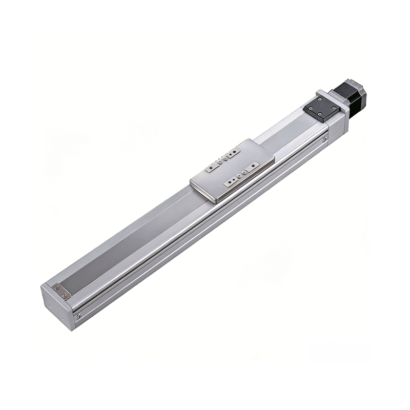 0.01mm High Precision Ball Screw Driven Rail-Embedded Linear Module
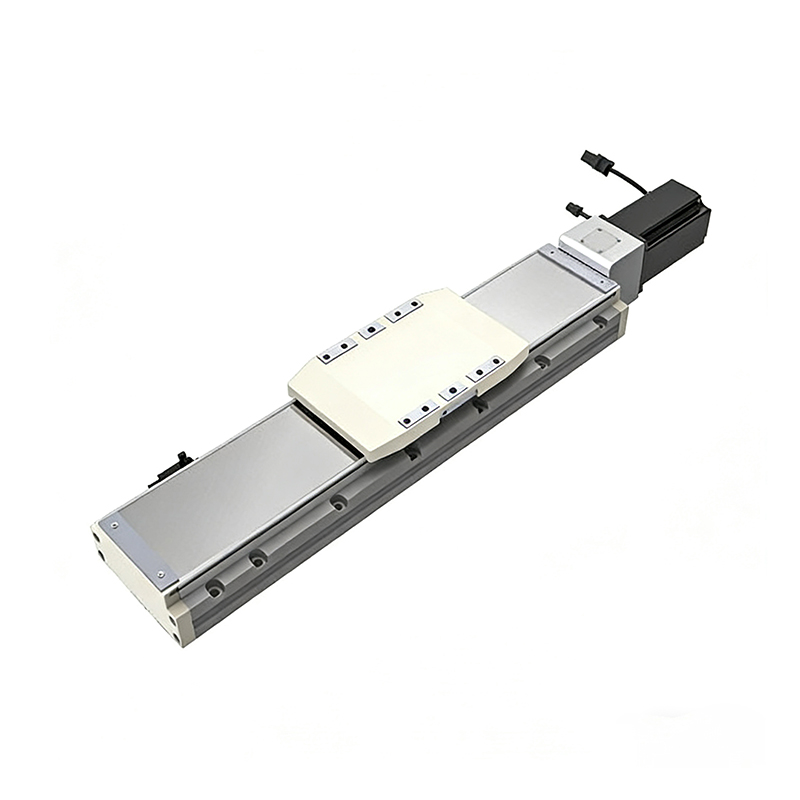 Heavy Load Ball Screw Driven Rail-Embedded Linear Module
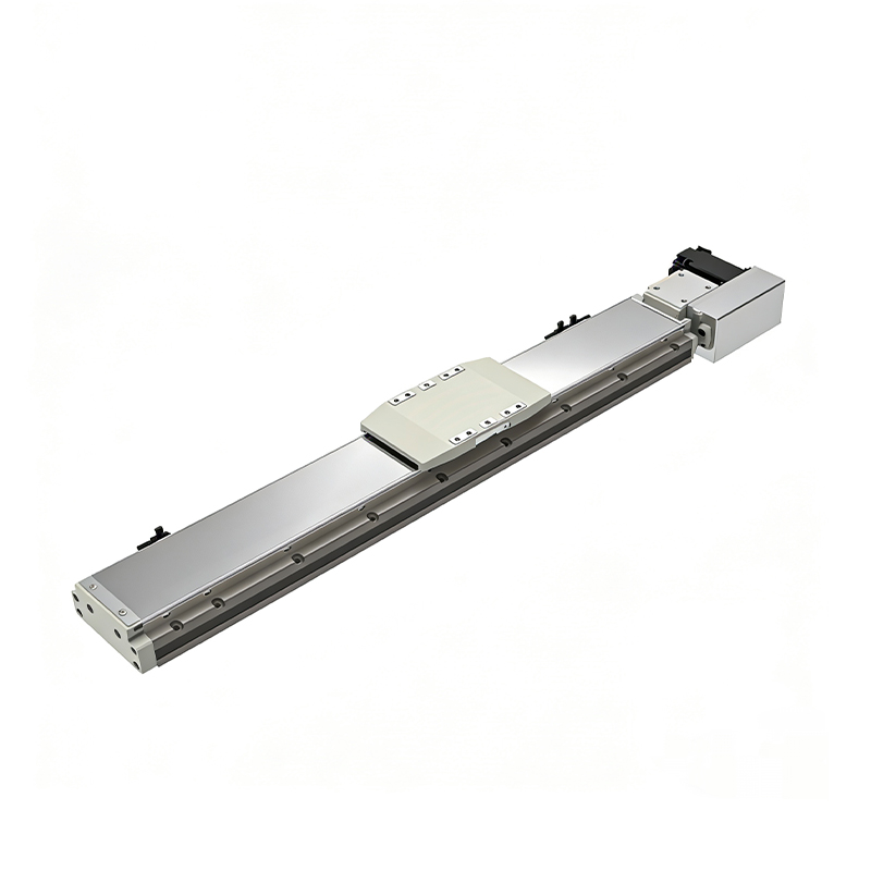 110KG Load Long Stroke Rail-Embedded Linear Module
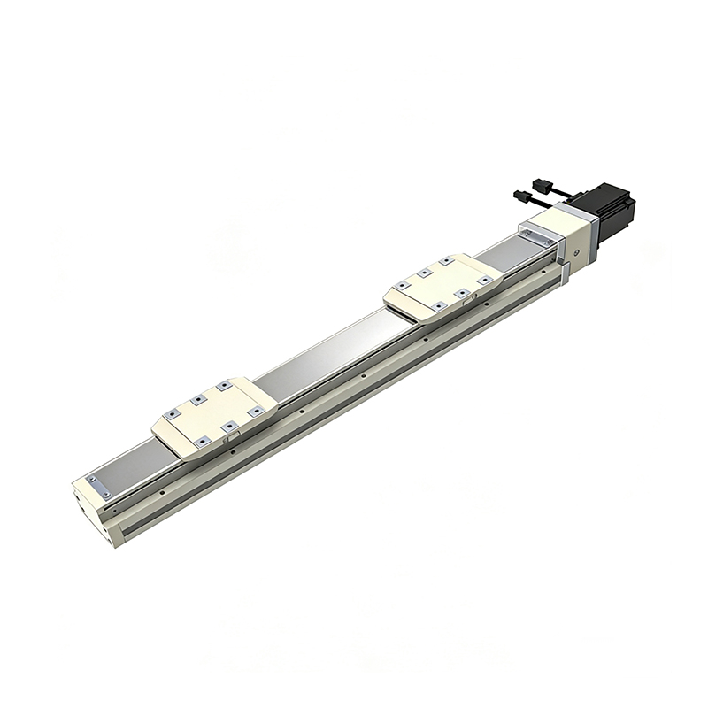 Dual-Slider High Precision Rail-Embedded Linear Module
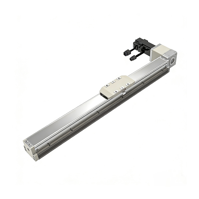 Belt Driven Dust-Proof Rail-Embedded Linear Module
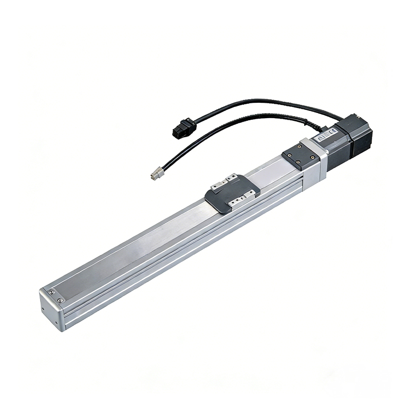 0.01mm High Precision Light Load Ball Screw Linear Module
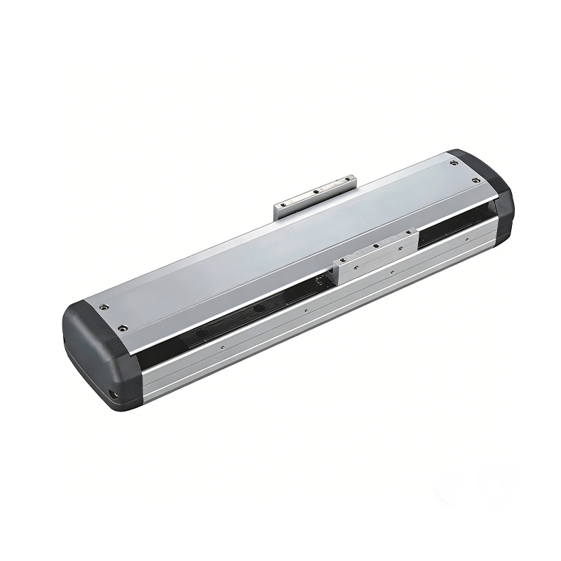 Ball Screw Linear Module with Built-in Sensor
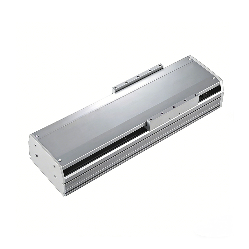 2000mm Long Stroke Ball Screw Linear Module
This 2000mm Long Stroke Ball Screw Linear Module is customized for large-range linear movement automation tasks, support...
READ MOREThis 2000mm Long Stroke Ball Screw Linear Module is customized for large-range linear movement automation tasks, support...
READ MOREThis 2000mm Long Stroke Ball Screw Linear Module is customized for large-range linear movement automation tasks, support...
READ MOREThis 2000mm Long Stroke Ball Screw Linear Module is customized for large-range linear movement automation tasks, support...
READ MORE
If you are interested in our products, please leave us a message. We look forward to providing you with
professional services!
Innovation and transcendence make factory intelligent manufacturing efficient and convenient!
+86 186 2508 0683
19962977901
sales@sz-tys.com
Building 5, Suzhou Mudu International Science and Technology Innovation Park, Jinfeng South Road, Suzhou City, Jiangsu Province, China
