


 English
 Français
 русский
 عربى
عربى Español
 Deutsch
Tel
+86 186 2508 0683

Manufacturing facilities across the world are shifting production lines toward equipment that can deliver repeatable accuracy while reducing energy waste. A servo press machine fits directly into this shift, because it replaces fixed mechanical motion with programmable slide control, letting a single machine handle multiple stamping tasks that once required several dedicated tools. The following sections break down where this technology is applied on the shop floor, what specifications matter when comparing models, and how sanitary servo-driven equipment is now used far beyond metal forming.
Structural brackets, seat frame reinforcements, and battery tray components require consistent forming force across thousands of daily cycles. A servo motor press machine allows the slide velocity to slow down at the point of contact, reducing shock loading on tooling and extending die life while holding tight dimensional tolerances on high-strength steel blanks.
Terminal pins, micro connectors, and shielding cases demand sub-millimeter repeatability. Because the drive system can be programmed with multiple pressure segments within a single stroke, forming, piercing, and sizing operations can occur in one cycle without transferring the part between separate stations.
Panels, brackets, and enclosure housings for household equipment are typically produced in high volume with moderate tonnage requirements. The programmable stroke profile allows manufacturers to switch between drawing depth settings without mechanical retooling of the drive train.
Fasteners, hinges, and structural fittings often move through progressive dies at high speed. Servo-driven slide control keeps the bottom dead center dwell consistent stroke after stroke, which stabilizes blanking edge quality and reduces burr formation over long production runs.
Battery housings and cell casings require deep drawing with controlled wall thinning. A servo hydraulic press machine is often selected for this application because the hydraulic circuit supplies the sustained pressure needed for deep-draw forming while the servo pump control limits energy draw during the non-forming portion of the cycle.
Compacting metal powders into net-shape parts benefits from pressure-hold segments that a servo drive can maintain accurately. This is particularly relevant when density uniformity across the part cross-section directly affects the sintering result later in the process chain.
Selecting the correct model depends on matching tonnage, stroke length, and table dimensions to the part geometry being produced. The reference figures below reflect commonly specified ranges for this equipment category across small, mid-range, and heavy-duty configurations.
| Model Class | Rated Tonnage | Stroke Length | Slide Adjustment | Table Dimension | Strokes per Minute |
| Compact Series | 25 - 60 tons | 60 - 120 mm | 50 mm | 500 x 700 mm | 40 - 200 |
| Mid-Range Series | 80 - 200 tons | 120 - 250 mm | 80 mm | 800 x 1200 mm | 25 - 120 |
| Heavy-Duty Series | 250 - 500 tons | 250 - 400 mm | 120 mm | 1200 x 1800 mm | 10 - 60 |
Buyers frequently need to weigh a fully electric servo drive against a servo-controlled hydraulic drive before finalizing an order. The table below outlines the operating characteristics that typically drive this decision.
| Comparison Item | servo motor press machine | servo hydraulic press machine |
| Energy Consumption | Lower average draw, motor idles at near-zero load between cycles | Reduced compared to fixed-displacement hydraulics, but higher than fully electric drive |
| Noise Level | 65 - 75 dB under load | 70 - 80 dB, quieter than conventional hydraulic units |
| Control Response | Millisecond-level slide position feedback | Closed-loop pressure and displacement feedback with slightly longer hydraulic response |
| Typical Tonnage Range | Best suited under 300 tons | Well suited above 300 tons and for deep-draw work |
| Maintenance Interval | Longer service intervals, no hydraulic fluid to manage | Requires scheduled fluid and filter checks |
| Ideal Application | High-speed stamping, progressive die work, electronics forming | Deep drawing, compaction, thick-plate forming |
Consistency in the final machine depends heavily on how the frame, drive components, and control system are produced and verified before shipment. The process below reflects the stages a stamping press typically passes through on the production floor.
Steel plate and casting components are checked for internal stress and dimensional accuracy before entering the machining stage.
Frame components, guide rails, and connecting rods are machined on CNC equipment to hold flatness and parallelism tolerances required for smooth slide travel.
The drive train, servo motor or hydraulic pump, and slide assembly are fitted together, then checked for vibration levels at operating speed.
Each unit is run under progressively increasing load to confirm rated tonnage, stroke accuracy, and control system response before being cleared for packing.
Exposed metal surfaces receive anti-rust treatment and the machine is secured for transport with moisture-resistant wrapping suited to long-distance shipping.
Because stamping lines rarely share identical layouts, most orders involve some degree of configuration beyond the base machine. The categories below cover the areas most commonly adjusted to match an existing production line.
Base tonnage can be specified according to material thickness and part depth, with intermediate steps available between standard model classes.
Stroke length and adjustable range can be modified to accommodate deeper draw depth or shorter high-speed blanking cycles.
Touchscreen programming supports multi-segment pressure curves, recipe storage for repeat jobs, and data logging for cycle count tracking.
Light curtains, dual-hand operation controls, and mechanical slide locking devices can be added according to the safety standard required at the installation site.
Coil feeding, decoiler, and straightening units can be synchronized with the servo control system to maintain consistent feed length across the full production run.
Servo control is not limited to metal forming. A cold pressed soft serve machine applies the same principle of programmable, low-shear motion to food processing, where the goal shifts from forming strength to preserving product texture and nutritional content. Instead of high-speed mechanical churning, the servo-driven plunger compresses the mix at a controlled rate and temperature, which limits air incorporation and heat generation during processing. This matters for recipes that rely on natural ingredients, since excess heat and agitation can break down flavor compounds and reduce the smoothness of the finished texture.
The construction of this equipment differs from stamping machinery in one key respect: every surface in contact with the product is built from food-grade stainless steel, with rounded internal corners that avoid product buildup and simplify cleaning between batches. Seals and gaskets are selected for repeated washdown cycles, and the drive housing is isolated from the product chamber to prevent any contamination path between the mechanical and food-contact zones.
| Specification | Typical Range |
| Output Capacity | 10 - 30 liters per hour |
| Processing Temperature | -5°C to 4°C |
| Compression Control | Programmable pressure segments via servo plunger drive |
| Contact Material | Food-grade stainless steel, sanitary finish |
| Cleaning Cycle | Tool-free disassembly for daily washdown |
Facilities producing small-batch or premium soft serve products often choose this format because it allows precise repeatability between batches, something that is difficult to achieve with manually controlled equipment. The same servo logic used to program a stamping cycle is applied here to hold a steady compression rate throughout the entire production run, regardless of small variations in mix viscosity.
What is the main advantage of a servo press machine over a mechanical flywheel press?
The slide motion is fully programmable rather than fixed by a flywheel and clutch, which means speed, dwell time, and pressure can be adjusted for each job without changing mechanical components.
How is tonnage selected for a new stamping application?
Tonnage is calculated from material thickness, shear strength, and the perimeter length being formed or cut, then a safety margin is added before matching the result to a model class.
When should a servo hydraulic press machine be chosen instead of a fully electric model?
Hydraulic drive is generally preferred above roughly 300 tons or for deep-draw and compaction work, where sustained pressure over a longer stroke is required.
Can a servo motor press machine run multiple different parts without retooling the drive system?
Yes, because the motion profile is stored as a program, operators can switch between saved recipes for different parts without adjusting the mechanical drive train itself.
What maintenance does a servo-driven press require compared to hydraulic equipment?
Electric servo systems avoid fluid changes and filter replacement, so maintenance focuses on lubrication points, encoder cleanliness, and periodic inspection of the connecting rod and guide rail assembly.
Is servo technology used outside of metal stamping?
Yes, the same programmable, low-shear motion principle is applied in food processing equipment such as a cold pressed soft serve machine, where controlled compression protects product texture.
The right configuration depends on part geometry, required tonnage, and the pace of production rather than a single universal answer. Lines running high-speed progressive dies on thinner material generally favor the fully electric drive train of a servo press machine, since the lower mechanical inertia allows faster cycling with less energy spent between strokes. Lines producing deep-drawn parts or working with thicker plate stock tend to benefit from the sustained force delivery of a hydraulic circuit, particularly where the forming pressure must be held steady across a longer portion of the stroke.
Position control precision on servo slide drive
Typical energy reduction versus mechanical flywheel drive
Maximum tonnage achievable with hydraulic servo circuits
Noise reduction compared to fixed-displacement hydraulic pumps
Part tolerance requirements also influence the decision. Electronics and connector work generally demands the fastest, most repeatable slide positioning, which points toward the electric drive category, while structural automotive components and battery casings often justify the added force capacity of a hydraulic system even at the cost of a slightly larger footprint and additional fluid maintenance.
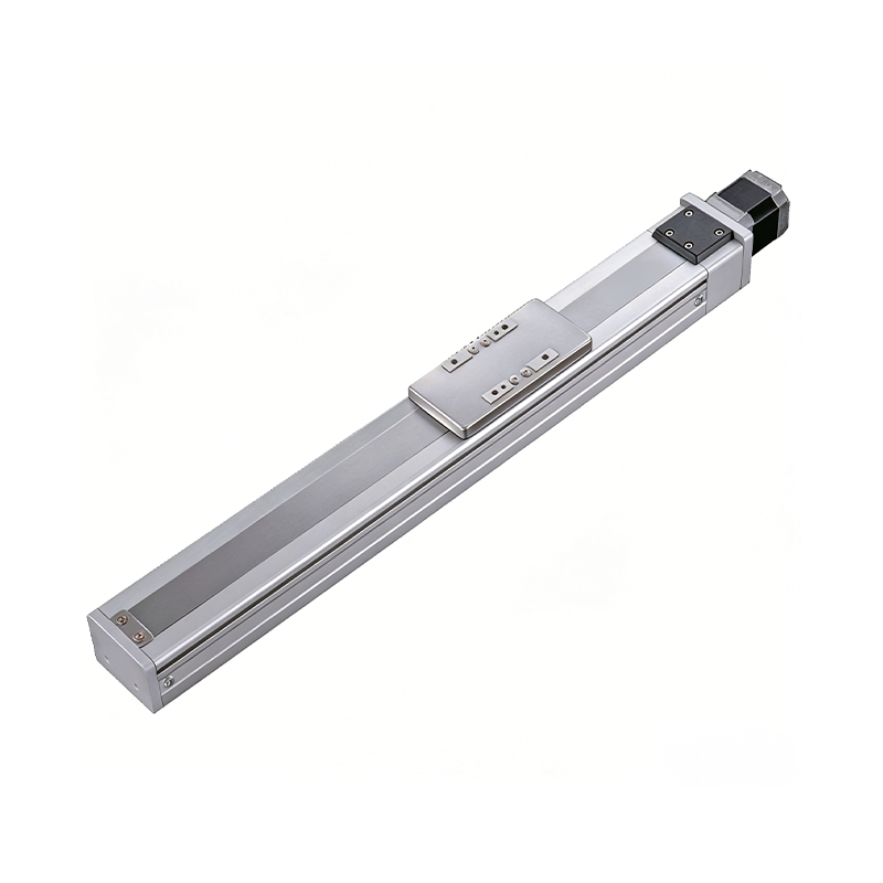 0.01mm High Precision Ball Screw Driven Rail-Embedded Linear Module
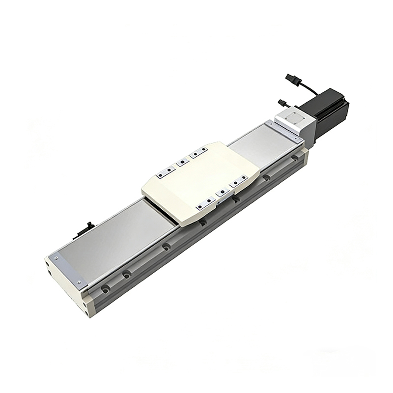 Heavy Load Ball Screw Driven Rail-Embedded Linear Module
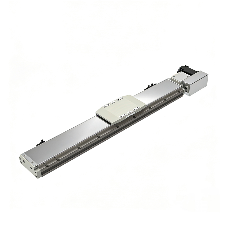 110KG Load Long Stroke Rail-Embedded Linear Module
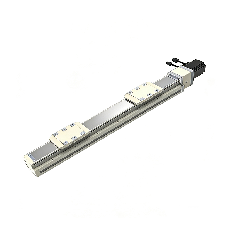 Dual-Slider High Precision Rail-Embedded Linear Module
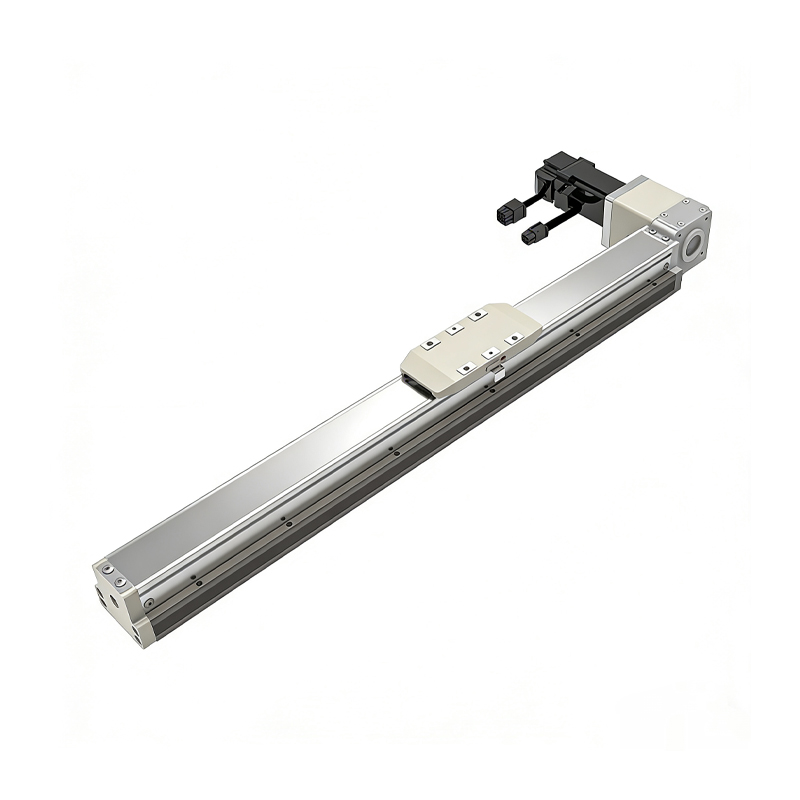 Belt Driven Dust-Proof Rail-Embedded Linear Module
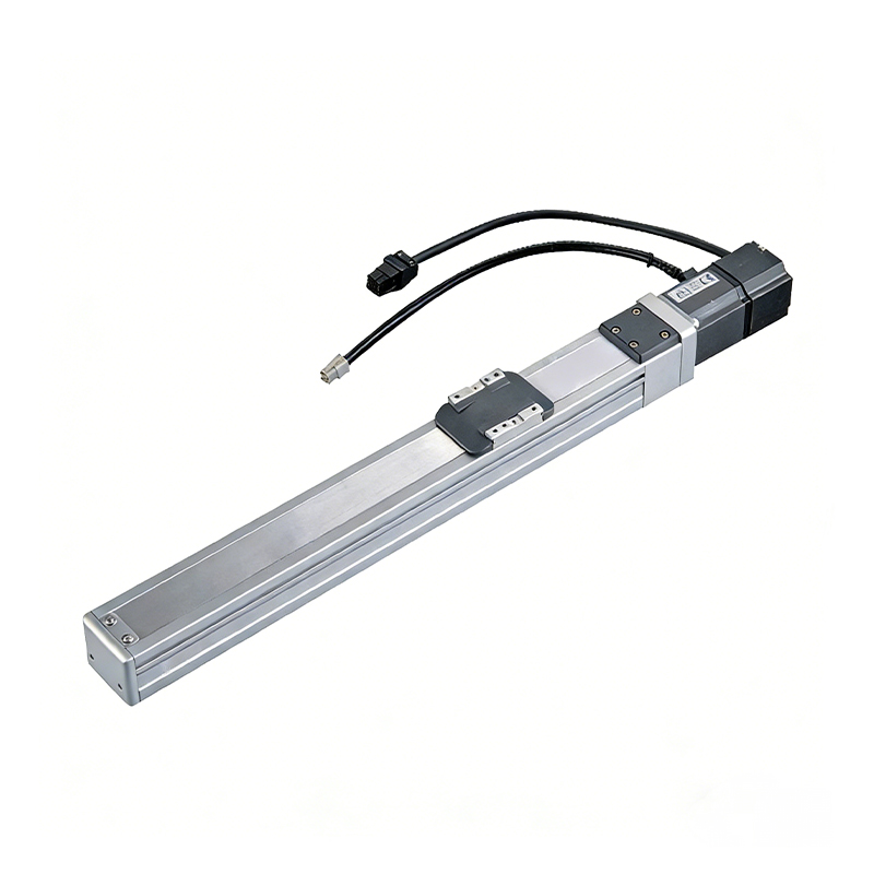 0.01mm High Precision Light Load Ball Screw Linear Module
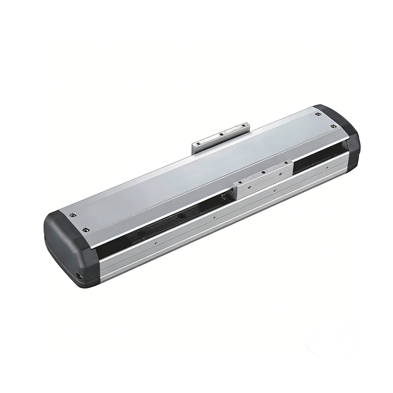 Ball Screw Linear Module with Built-in Sensor
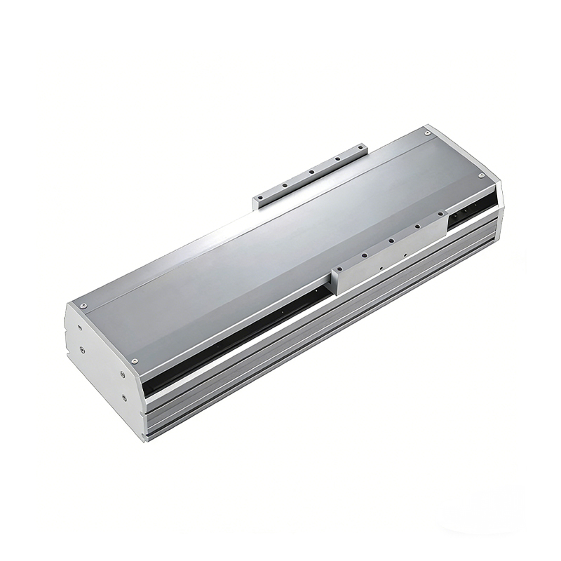 2000mm Long Stroke Ball Screw Linear Module
This 2000mm Long Stroke Ball Screw Linear Module is customized for large-range linear movement automation tasks, support...
READ MOREThis 2000mm Long Stroke Ball Screw Linear Module is customized for large-range linear movement automation tasks, support...
READ MOREThis 2000mm Long Stroke Ball Screw Linear Module is customized for large-range linear movement automation tasks, support...
READ MOREThis 2000mm Long Stroke Ball Screw Linear Module is customized for large-range linear movement automation tasks, support...
READ MORE
If you are interested in our products, please leave us a message. We look forward to providing you with
professional services!
Innovation and transcendence make factory intelligent manufacturing efficient and convenient!
+86 186 2508 0683
19962977901
sales@sz-tys.com
Building 5, Suzhou Mudu International Science and Technology Innovation Park, Jinfeng South Road, Suzhou City, Jiangsu Province, China
