


 English
 Français
 русский
 عربى
عربى Español
 Deutsch
Tel
+86 186 2508 0683

A packaging machine builder once specified a 500 mm stroke electric cylinder for a vertical lift. The load was only 40 kg, so the actuator looked oversized. Six weeks after commissioning, the rod seal was leaking and the guide rails showed visible scoring. The problem was not the load rating. It was the 300 mm off-center mounting that turned a pure thrust application into a side-load problem. That single mistake cost more than the actuator itself in downtime and rework.
Linear actuator selection is rarely about finding the biggest force number in a catalog. It is about matching a motion profile, a mechanical envelope, an environment, and a control system to a specific machine cycle. The right actuator is the one that survives the 10-millionth cycle, not the one that looks best on a data sheet. Below is a practical sequence for choosing the right linear actuator, with the specific checks that separate a reliable design from an expensive experiment.
Before comparing actuators, write down the motion requirements in numbers. At minimum, you need:
A common failure is to define only load and stroke. Speed and duty cycle determine the motor, screw lead, and thermal margin. A unit rated for 2 kN static thrust may only deliver 600 N continuously at 1,000 mm/s with a 60% duty cycle. If the application runs 24/7, that difference decides whether the actuator lasts two years or two months.
Use a simple worksheet. List every axis, the worst-case load, the required speed, and the percentage of time the actuator is moving. Then calculate RMS force and RMS speed. These values, not the peak numbers, drive thermal sizing. A data sheet peak rating is useful for acceleration, but continuous rating is what keeps the motor and screw within temperature limits.
| Parameter | Why it matters | Common mistake |
|---|---|---|
| Peak thrust | Sizes the screw, bearings, and motor torque for acceleration and work stroke. | Using only average load and ignoring acceleration spikes. |
| Continuous thrust | Sets thermal limits for motor, drive, and screw nut. | Assuming peak rating can be held indefinitely. |
| Speed and acceleration | Determines screw lead, motor RPM, and stability. | Choosing a fine lead for precision, then finding it cannot reach cycle time. |
| Duty cycle | Controls heat buildup and lubrication life. | Ignoring that a 10% duty rating cannot run 80% of the time. |
| Side and moment load | Protects bearings, guides, and seals. | Mounting a rod-style actuator without external guidance. |
Once the motion profile is clear, the drive train becomes a trade study. Ball screws, lead screws, timing belts, rack and pinion, and linear motors each have a performance envelope. There is no universal best choice.
For many industrial machines, the electric cylinder is the fastest route to a robust linear actuator. It packages a motor, screw, nut, bearings, and rod into a sealed unit. If the application needs a guided carriage rather than a pushing rod, a linear module with an integrated rail is a better fit. The choice is mechanical architecture, not brand preference.
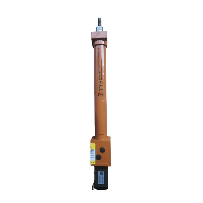 Electric Cylinder Actuators for Industrial AutomationExplore customizable electric cylinder actuators with servo closed-loop control, precision lead screw drive, and multiple mounting families for varied linear motion needs.View Product →
These three families overlap, but they solve different mounting and guidance problems.
An electric cylinder produces linear motion through a rod. It is the closest replacement for a pneumatic or hydraulic cylinder. It excels in pressing, lifting, clamping, and valve actuation. The rod can accept a clevis, flange, or threaded end. The main limitation is side load: unless the rod is externally guided, all side and moment loads must be avoided. Inline, foldback, telescopic, and waterproof versions cover most industrial envelopes.
A linear module carries the load on a carriage that rides on a guide rail. The drive can be a ball screw, belt, or rack and pinion. Because the rail handles side and moment loads, a linear module is the right choice for cantilevered tooling, gantries, and multi-axis systems. Stroke can be long, and multiple carriages can run on one rail. Precision grades range from general transfer to sub-0.1 mm positioning.
A linear motor module replaces the screw or belt with a direct-drive linear motor. It delivers the highest speed and acceleration, often above 3 g, with no backlash or wear particles from a drive train. It is the preferred solution for semiconductor, electronics, and high-throughput inspection. The trade-off is cost, control complexity, and the need to manage heat and magnetic attraction.
A useful rule: if the load is a push or pull along the rod axis, start with an electric cylinder. If the load is offset or needs to travel on a carriage, start with a linear module. If the cycle demands more than 2 m/s or 2 g, evaluate a linear motor module.
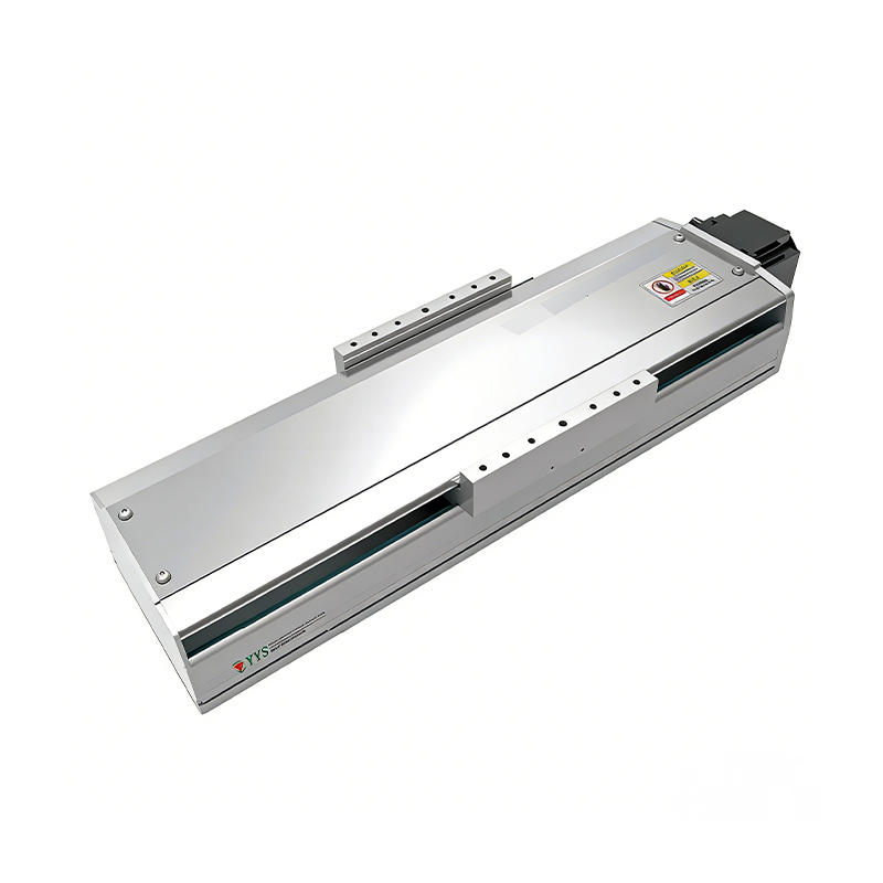 320KG Heavy Load Ball Screw Linear ModuleFor offset or carriage loads, this heavy-duty ball screw module offers high rigidity, up to 320 kg horizontal payload, and 50–1950 mm stroke.View Product →
Environment often eliminates more options than performance does. A standard actuator with an IP54 rating will fail in a washdown area, and a stainless steel body does not guarantee protection for the motor and feedback system.
For dust and splash, look for IP65. For temporary immersion or frequent washdown, IP68 is the minimum. In chemical processing, the actuator may also need a corrosion-resistant coating, stainless hardware, and a sealed cable entry. Explosion-proof areas require a motor and housing certified for the hazardous zone, not just a sealed enclosure. Wide-temperature ranges demand special lubrication, seals, and motor insulation. A standard unit rated for 0 to 40 degrees Celsius may not start reliably at minus 20 or survive a 60-degree ambient.
Environmental checks should include:
If the application is in an automated assembly line, the actuator may also need to meet cycle-time and contamination requirements specific to that industry. For example, a chemical processing environment may demand both IP68 and chemical-resistant seals, while a cleanroom semiconductor tool may prioritize low particle generation.
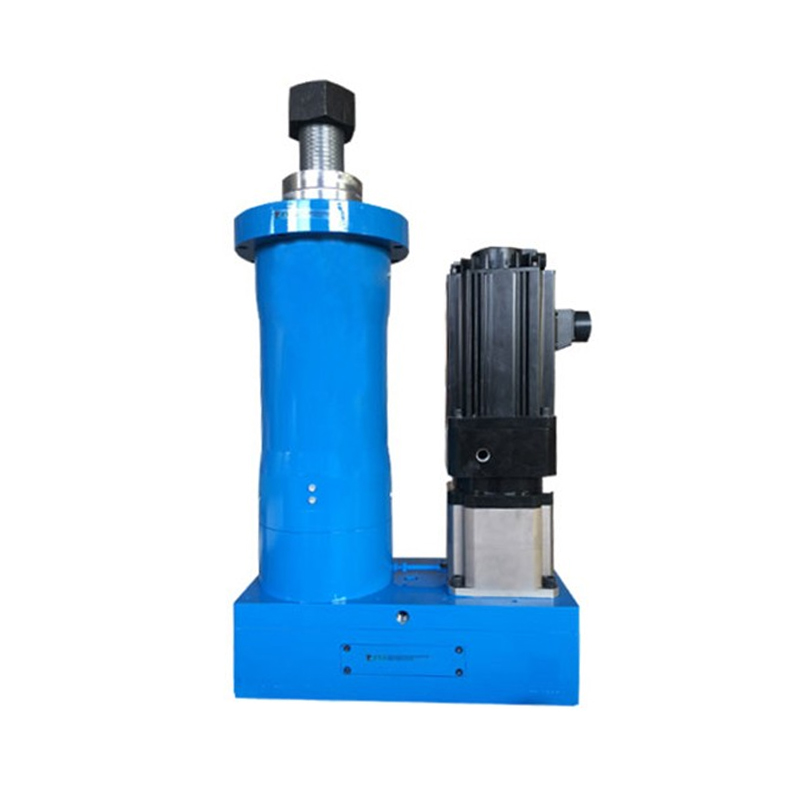 IP65 Splash-Proof Waterproof Electric Cylinder TYSC220For dusty, splash-prone environments, this IP65 electric cylinder uses waterproof seals, dust cover, and aluminum alloy body; TYSC220 delivers 200 kN rated force.View Product →
Linear actuator life is usually limited by lubrication, bearing fatigue, or motor winding temperature. The data sheet life rating assumes a specific load, speed, and duty cycle. Real applications rarely match those assumptions.
Calculate the following:
If the RMS values exceed the continuous rating, choose a larger frame, a lower lead, or a different drive train. Do not simply add a cooling fan. A fan may help the motor, but the screw nut and seals may still overheat. For high-duty applications, a ball screw with a larger diameter and a lower lead often runs cooler than a small, fast screw.
Many selection failures come from ignoring duty cycle. A high-power electric cylinder rated for 10% duty can be pushed to 50% only with derating and additional cooling. If the machine runs three shifts, that difference is not a detail. It is the basis of the warranty. Our own field data and industry reports point to the same pattern: three critical selection mistakes account for most premature failures, and duty cycle misunderstanding is one of them.
Mechanical integration decides whether the actuator reaches its rated life. Even a perfectly sized actuator will fail if it is misaligned, overhung, or mounted on a flexible frame.
On the control side, match the actuator to the drive and controller. Stepper motors are simple and low cost, but they can lose position under overload. Servo motors provide closed-loop control, higher speed, and better torque at high speed. Integrated actuators with built-in drives simplify wiring but may limit the choice of controller. If the machine uses an EtherCAT, CANopen, or Modbus network, verify that the actuator's drive supports the same protocol and cycle time.
Also check feedback resolution. A 0.1 mm repeatability specification may be meaningless if the mechanical backlash, coupling windup, and thermal expansion add up to 0.5 mm. For precision assembly, specify the repeatability at the load point, not at the motor shaft.
Use this sequence to move from requirements to a verified selection:
The most reliable projects treat the actuator as part of a system. A supplier who can show test data, calculate duty cycle, and recommend the right screw lead is more valuable than a catalog with impressive peak numbers. For machine builders, that support reduces the risk of a late-stage redesign.
Choosing the right linear actuator comes down to a disciplined comparison. Start with the motion profile. Match the drive train and mechanical family to the load path. Check the environment before the control architecture. Calculate RMS values and thermal margin. Verify mounting and alignment. Then test the worst-case cycle. If you follow that sequence, the actuator becomes a predictable component rather than a recurring maintenance item.
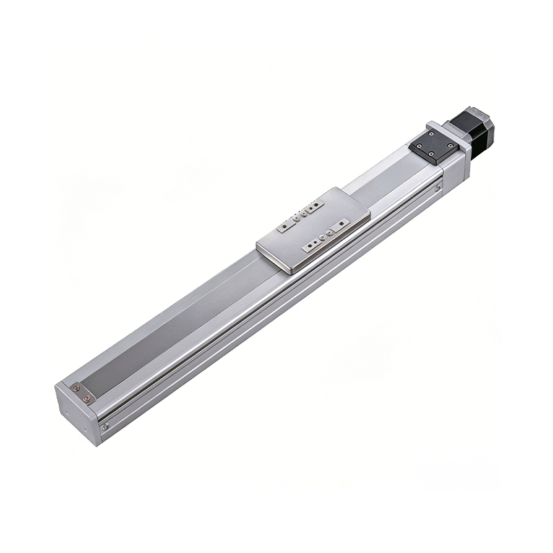 0.01mm High Precision Ball Screw Driven Rail-Embedded Linear Module
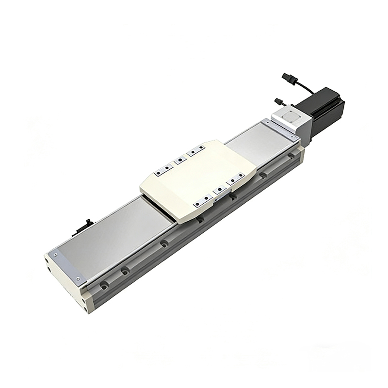 Heavy Load Ball Screw Driven Rail-Embedded Linear Module
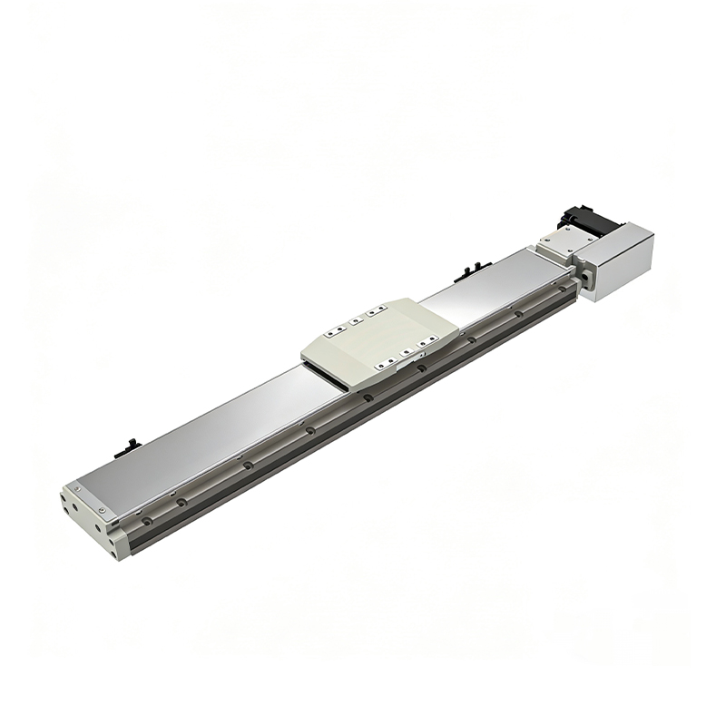 110KG Load Long Stroke Rail-Embedded Linear Module
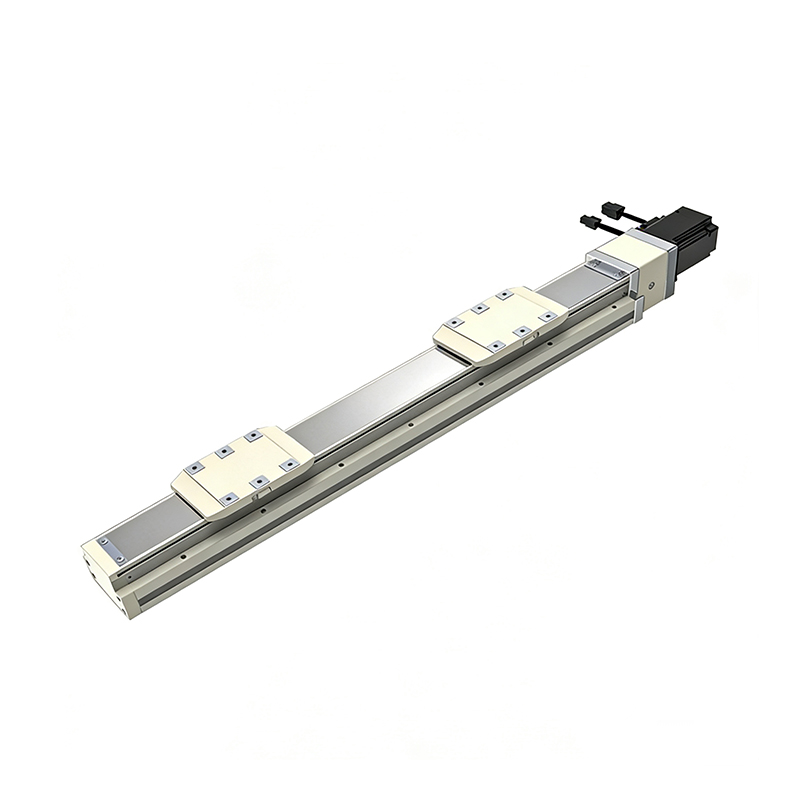 Dual-Slider High Precision Rail-Embedded Linear Module
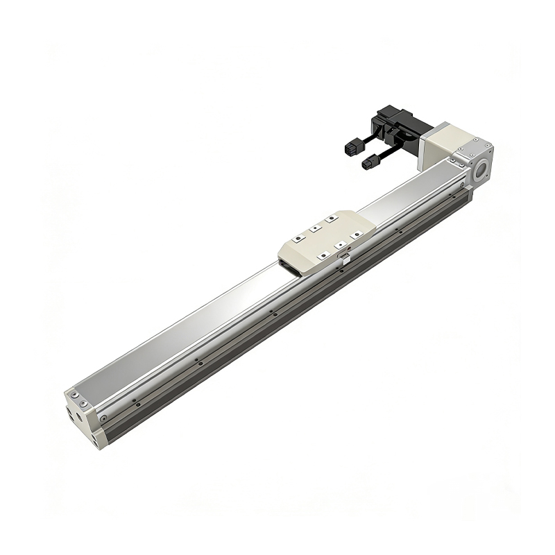 Belt Driven Dust-Proof Rail-Embedded Linear Module
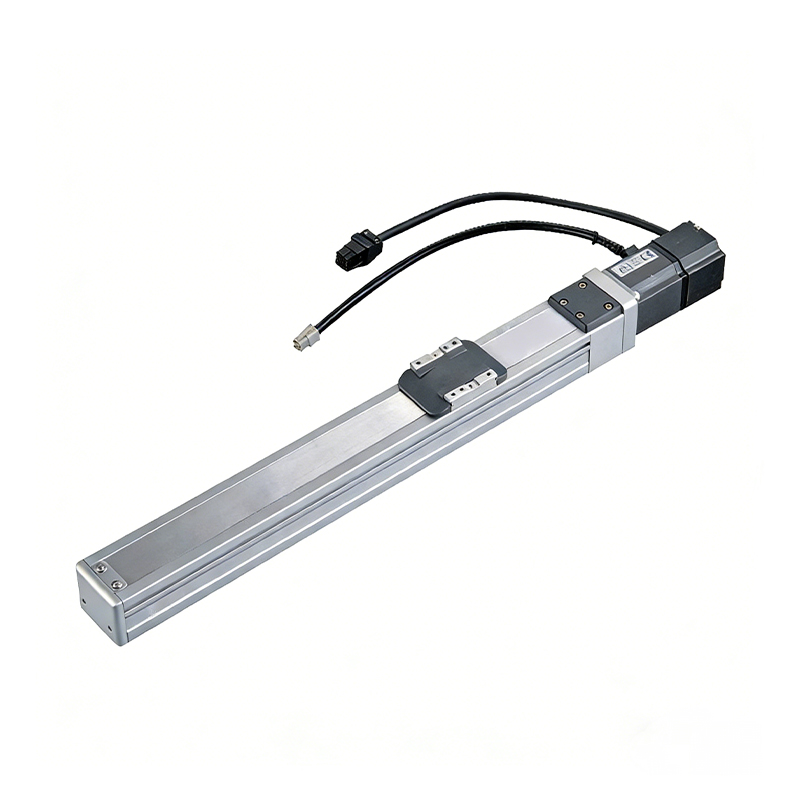 0.01mm High Precision Light Load Ball Screw Linear Module
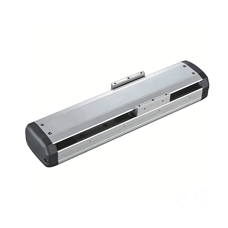 Ball Screw Linear Module with Built-in Sensor
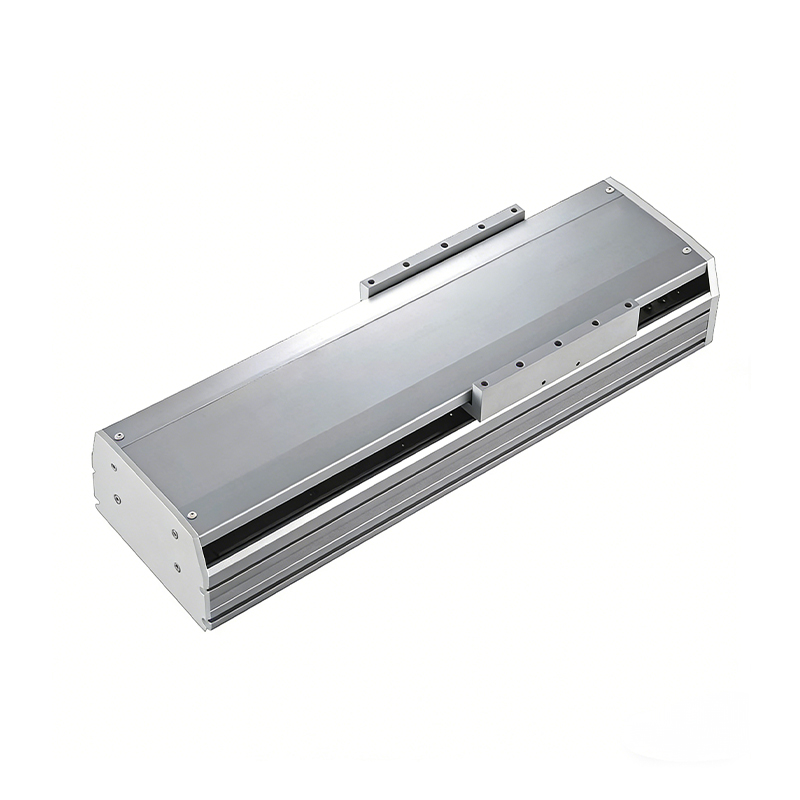 2000mm Long Stroke Ball Screw Linear Module
This 2000mm Long Stroke Ball Screw Linear Module is customized for large-range linear movement automation tasks, support...
READ MOREThis 2000mm Long Stroke Ball Screw Linear Module is customized for large-range linear movement automation tasks, support...
READ MOREThis 2000mm Long Stroke Ball Screw Linear Module is customized for large-range linear movement automation tasks, support...
READ MOREThis 2000mm Long Stroke Ball Screw Linear Module is customized for large-range linear movement automation tasks, support...
READ MORE
If you are interested in our products, please leave us a message. We look forward to providing you with
professional services!
Innovation and transcendence make factory intelligent manufacturing efficient and convenient!
+86 186 2508 0683
19962977901
sales@sz-tys.com
Building 5, Suzhou Mudu International Science and Technology Innovation Park, Jinfeng South Road, Suzhou City, Jiangsu Province, China
