


 English
 Français
 русский
 عربى
عربى Español
 Deutsch
Tel
+86 186 2508 0683

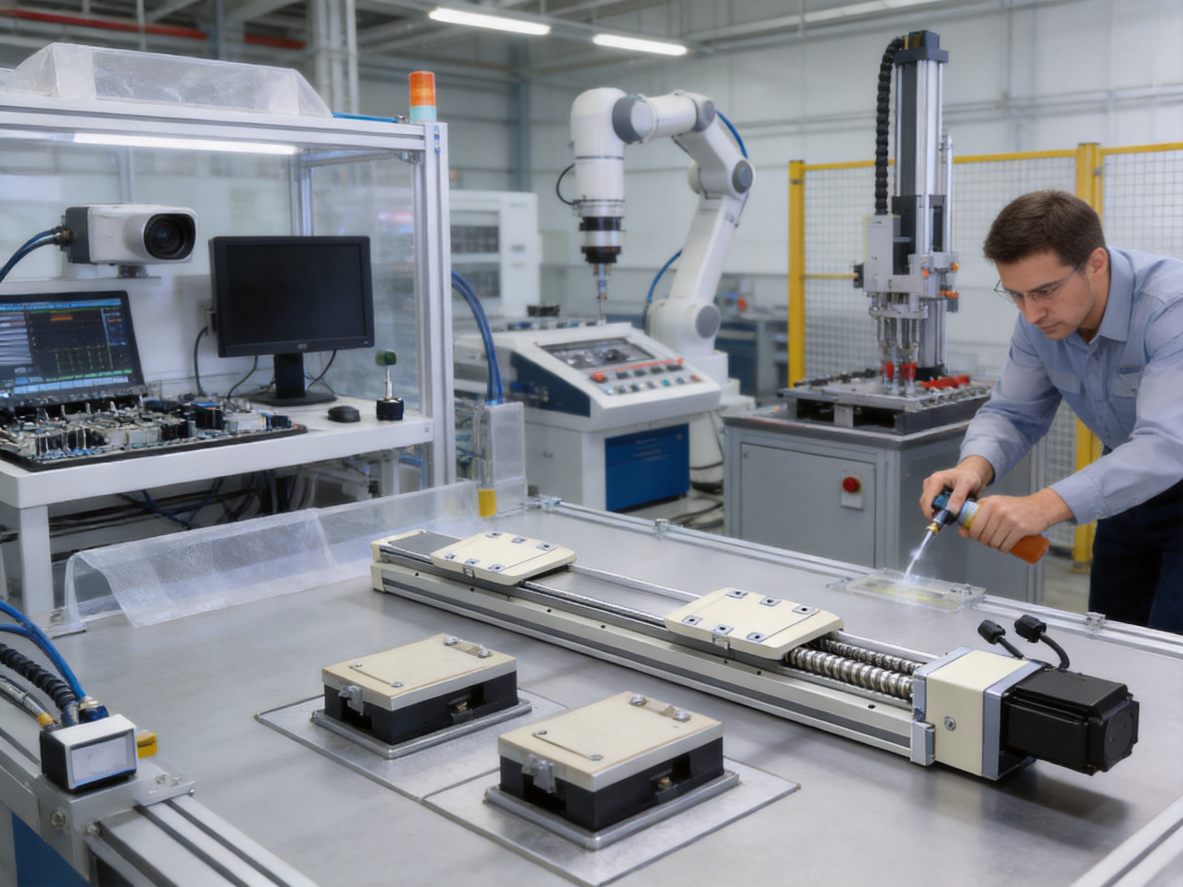
Modern automation systems increasingly require motion components that combine precision, rigidity, flexibility, and dependable service life. Whether used in electronic assembly, inspection equipment, robotic handling, precision alignment, or automated testing, a linear module must do more than move a load from one point to another. It must maintain stable guidance, resist uneven loading, support repeatable positioning, integrate smoothly with control systems, and deliver reliable performance over extended operating cycles.
The Dual-Slider High-Precision Rail-Embedded Linear Module is designed for these demanding requirements. With two sliding blocks, an embedded high-precision rail structure, a ball screw transmission system, and a 400 W AC servo motor configuration, the module provides a balanced solution for applications that need both mechanical stability and programmable motion control. Its dual-slider architecture distributes loads more evenly than many single-slider designs, while also allowing synchronized or independent movement strategies according to the machine configuration.
The module is suitable for horizontal, vertical, and wall-mounted installations when the application is properly evaluated. It offers a repeatability of ±0.01 mm, a maximum speed of 250 mm/s, a rated thrust of 1,388 N, and available strokes from 25 mm to 450 mm in 25 mm increments. Its maximum payload is up to 50 kg in horizontal dual-carriage operation and up to 15 kg in vertical dual-carriage operation, subject to installation conditions, center of gravity, overhang, acceleration, and duty cycle.
This article examines the product structure, operating advantages, specifications, manufacturing strengths, application value, installation considerations, and selection guidance of the Dual-Slider High-Precision Rail-Embedded Linear Module. It also explains why a well-engineered dual-slider module can provide important advantages over conventional single-slider solutions and less integrated linear positioning products.
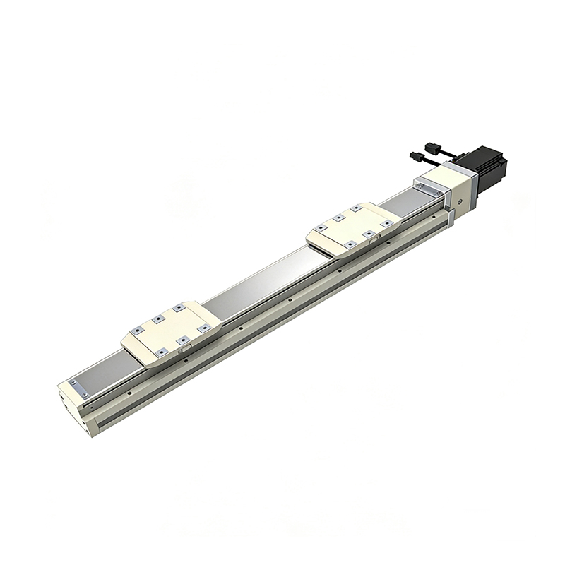
Dual-Slider High Precision Rail-Embedded Linear Module
The Dual-Slider High-Precision Rail-Embedded Linear Module is a compact electromechanical positioning unit built around a precision guide rail and ball screw transmission. Its primary purpose is to provide controlled linear motion with a high degree of repeatability, stable load support, and convenient integration into automated equipment.
The two sliding blocks are the defining feature of the design. Instead of concentrating the working load on one carriage, the dual-slider arrangement creates two support points along the guide path. This increases load-bearing uniformity and helps reduce the influence of eccentric loads. When a workpiece, gripper, fixture, or tooling assembly extends away from the centerline, the spacing and combined support of the two sliders can improve stability and reduce unwanted tilting.
The two carriages may be used in a synchronized manner when both must move together, or they may be configured for separate positioning functions where the machine architecture permits independent control. This provides greater flexibility than a basic single-carriage module. For example, two fixtures can be positioned at different locations, two workpieces can be handled in sequence, or a pair of grippers can operate in parallel.
The rail-embedded structure integrates the guidance components into the module body. This arrangement contributes to a neat external profile and protects critical motion elements from some environmental interference. It also helps simplify machine layout, because the module can act as a self-contained motion axis rather than requiring a separate guide rail, support structure, and transmission assembly to be designed around it.
A ball screw with a 5 mm lead provides the transmission mechanism. The selected lead offers a useful balance between thrust capability, positioning resolution, and travel speed. The module is therefore suitable for applications where controlled force and repeatable positioning are more important than extremely high linear velocity.
The principal performance characteristics of the module include ±0.01 mm repeatability, a maximum speed of 250 mm/s, a rated thrust of 1,388 N, and a maximum horizontal payload of 50 kg with the dual carriage. In vertical applications, the maximum payload is specified as 15 kg with the dual carriage. These figures should be interpreted together with the actual installation orientation, load distribution, center of gravity, acceleration profile, and operating frequency.
The available stroke range extends from 25 mm to 450 mm at 25 mm intervals. This provides a broad selection of travel lengths for compact transfer mechanisms, inspection stations, indexing systems, positioning tables, and robotic end-effectors. Standardized stroke increments can simplify design selection, procurement, replacement, and maintenance.
The guide and transmission system are matched with a 400 W AC servo motor output. Compatible motor options include Mitsubishi, Panasonic, and Delta configurations, with both brake and no-brake versions available depending on the installation orientation. Horizontal systems generally use motors without a brake, while vertical systems may require a brake to help hold the load safely when power is removed.
One of the most important advantages of the dual-slider design is improved load distribution. A single carriage can support a load effectively when the load is centered and the overhang is limited. However, as the load becomes wider, heavier, or more eccentric, the carriage may experience increased moment loading. This can influence running smoothness, rail wear, positioning consistency, and long-term mechanical stability.
Two sliding blocks provide a longer and more balanced support arrangement. The distance between the support points helps distribute forces along the guide rail and reduces the concentration of load on one localized area. This is particularly valuable when the module carries a broad fixture, a multiple-point handling device, or an assembly tool with a center of gravity that is not directly above the transmission axis.
Improved distribution does not mean that the module can be operated without engineering limits. The application must still remain within the specified payload, moment, overhang, and speed conditions. Nevertheless, the dual-slider arrangement offers a stronger mechanical foundation for demanding loads than many single-slider layouts of similar size.
Movement stability is essential in precision automation. Vibration, yaw, pitch, or roll during acceleration and deceleration can affect the quality of assembly, dispensing, inspection, screwdriving, probing, and testing operations. The two-carriage support system helps stabilize the moving platform, especially when the payload is distributed across a larger area.
A stable moving surface also benefits sensors and tooling. Cameras, measuring probes, laser heads, grippers, and alignment devices can operate more consistently when the supporting axis exhibits limited deflection and smooth travel. The result can be improved process repeatability and fewer adjustments during production.
The dual-slider configuration supports two different mechanical strategies. In synchronized operation, both sliders move as a coordinated pair to carry a common fixture or workpiece. This is useful for transfer platforms, parallel grippers, long tooling plates, and handling mechanisms that require balanced movement.
In suitable system configurations, the sliders may also be used for independent positioning. This enables two workstations, two fixtures, or two handling points to share one linear module. Such an arrangement may reduce the number of separate axes required in a machine and can help save installation space.
Independent operation should be specified carefully because the exact control architecture, transmission arrangement, and motor configuration determine how the sliders are driven and coordinated. The feature is best treated as a design flexibility that must be confirmed during technical review rather than assumed for every standard configuration.
Many automation builders must fit several axes, sensors, cables, tooling systems, and protective components into a limited machine envelope. An integrated rail-embedded module can reduce the need for separate guide assemblies and external support components. This can simplify the mechanical layout and provide a cleaner axis installation.
The compact structure is especially helpful in electronic manufacturing equipment, inspection systems, laboratory automation, and small robotic cells. A shorter installation envelope can make it easier to position the axis near other mechanisms while maintaining access for assembly and maintenance.
Eccentric loads occur when the center of gravity is offset from the center of the guide or screw. Examples include a gripper mounted on a side plate, a tall workpiece held above the carriage, or a tooling assembly that extends forward from the axis. These conditions create static and dynamic moments.
The module provides specified static loading moment values of 318 N·m for MY, 318 N·m for MP, and 626 N·m for MR. The torque values represent the center of gravity conditions stated in the product information. Designers should use these values as reference limits and confirm the actual load case with the supplier, especially when the application includes rapid acceleration, frequent reversals, cantilevered tooling, or vertical operation.
The ball screw is a critical component in the module’s positioning system. A 5 mm lead means that one complete screw revolution advances the nut by 5 mm. This relatively moderate lead is well suited to applications that require controlled movement, useful thrust, and fine position adjustment.
Compared with a high-lead screw, a 5 mm lead can provide greater mechanical advantage and better thrust capability for the same motor torque. This is beneficial in pressing, clamping, lifting, feeding, and precision transfer applications. The rated thrust of 1,388 N reflects the module’s ability to generate substantial linear force within the specified operating conditions.
The ball screw is specified as C7 with a 16 mm diameter. The C7 grade is commonly used in industrial positioning systems where repeatability and cost efficiency must be balanced. Actual positioning performance depends not only on screw grade but also on preload, bearing support, machining accuracy, servo tuning, thermal conditions, lubrication, installation alignment, and load behavior.
The integrated guide rail provides the moving blocks with a controlled path and supports the loads generated during operation. Embedding the rail into the module structure helps maintain the relationship between the guide and transmission components. This is important because misalignment between a guide rail and a ball screw can increase friction, generate vibration, and reduce service life.
A properly manufactured embedded rail structure can also improve repeatability during installation. Rather than requiring the customer to align several independent components, the module is supplied as a coordinated assembly. This can shorten machine-building time and reduce the possibility of assembly errors.
The two sliding blocks further improve the guidance arrangement by providing distributed support over the carriage area. When the moving platform is correctly mounted and the load is within specification, the arrangement helps maintain smooth motion during acceleration, constant-speed travel, and deceleration.
The specified repeatability of ±0.01 mm makes the module appropriate for many precision automation tasks. Repeatability describes the ability of the axis to return to a position under comparable conditions. It is especially important in repetitive operations such as component placement, camera inspection, probe contact, automatic testing, dispensing, and alignment.
Repeatability is not identical to absolute accuracy. Absolute accuracy refers to how closely the actual position matches the commanded position across the full travel range. To achieve the best practical results, the machine designer should evaluate both repeatability and accuracy requirements. Servo tuning, encoder resolution, mechanical backlash, thermal growth, workpiece variation, and external vibration all influence final system performance.
Horizontal installation provides the highest stated payload capacity. The dual carriage can support up to 50 kg horizontally, although the allowable load also depends on how the load is distributed and how far it extends from the guide centerline.
The overhang reference data includes load conditions of 20 kg, 35 kg, and 50 kg. The listed values describe allowable dimensions associated with A, B, and C directions for the specified load cases. These figures should be used during preliminary design to prevent excessive cantilevering. If the payload extends too far beyond the supported region, the resulting moment can exceed the guide or carriage capacity even when the total mass is below 50 kg.
Horizontal applications commonly include workpiece transfer, pallet movement, inspection positioning, feeding systems, robotic subassemblies, and horizontal indexing. For high-cycle applications, the machine builder should also account for acceleration and deceleration forces, because dynamic loads may be significantly greater than static payload values.
Wall-mounted installation is useful when the module must operate on a vertical plane while the movement direction remains horizontal. This configuration can save floor space and allow the axis to work as part of a side-mounted handling or inspection system.
The product information provides separate overhang reference data for wall-mounted use. These values differ from the horizontal installation data because the direction of gravity and the associated moment loads change. The mounting frame must have sufficient rigidity, and the fasteners must be selected according to the actual load and acceleration conditions.
When wall mounting is used with a heavy or eccentric tool, the designer should check the combined effects of gravity, acceleration, braking, and cable drag. A rigid base and correctly distributed mounting points are essential for preserving the module’s precision.
Vertical installation is suitable for lifting, lowering, feeding, stacking, pressing preparation, and height adjustment. The maximum vertical payload is specified as 15 kg with the dual carriage. The lower payload rating reflects the additional force required to overcome gravity and the increased safety requirements associated with suspended loads.
A brake-equipped servo motor is recommended for vertical applications. The brake helps hold the moving assembly when the servo is disabled or when power is interrupted. However, a motor brake should not be treated as the only safety measure. Depending on the risk assessment, the machine may also require mechanical stops, counterbalance systems, safety-rated controls, guarding, load monitoring, or an independent fall-prevention mechanism.
The standard specifications do not apply to ceiling-mounted inverted use. Any inverted or overhead installation should be reviewed with the supplier before implementation. Such a configuration may change lubrication behavior, mounting requirements, load paths, and safety considerations.
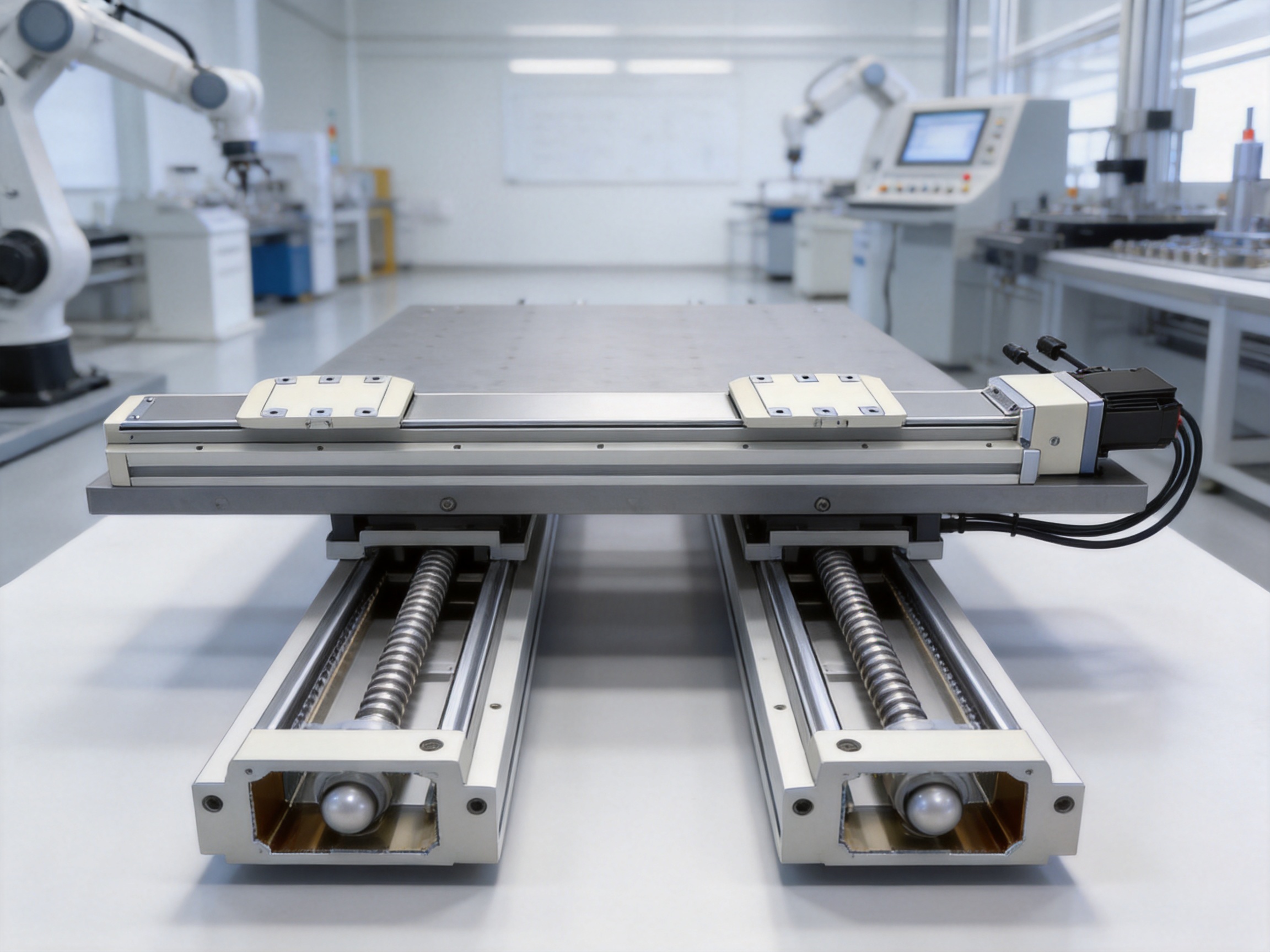
The module is available with several motor orientation options, including motor right side, motor left side, motor exposed, and motor bottom side. These alternatives allow machine designers to select a configuration that best matches the available installation space and cable routing requirements.
For motor-right, motor-left, and motor-bottom-side configurations, the overall length L changes according to the selected stroke. The standard stroke range is 25 mm to 450 mm. The motor-exposed configuration has slightly different overall length values, reflecting the external motor arrangement.
For many configurations, the A dimension alternates between 50 mm and 100 mm as the stroke increases in 25 mm increments. The M, N, and P dimensions also change according to the stroke selection. These dimensions are important when planning mounting holes, machine frames, protective covers, cable chains, and adjacent axes.
The product tables also list the approximate module weight in kilograms for each stroke. Weight increases as the stroke becomes longer because of the extended body and screw assembly. Machine builders should include the module’s own mass when calculating the load on a supporting axis, robot, frame, or lifting mechanism.
When the stroke is 50 mm, the top-locking mounting holes on the main body may be blocked by the slider. In that condition, only four screws can be used for fixation through the affected mounting arrangement. The recommended solution is to secure the main body using the bottom-locking mounting holes.
This detail is important during mechanical design because short-stroke modules often have limited clearance between the moving block and the mounting holes. The machine builder should confirm tool access before finalizing the base plate and should ensure that the selected mounting method provides adequate rigidity and fastener engagement.
The module is designed for a 400 W AC servo motor output and can be configured with motor and driver combinations from several established industrial automation suppliers. The available options include Mitsubishi, Panasonic, and Delta systems.
For Mitsubishi, the horizontal configuration may use the HG-KN43J-S100 motor with the MR-JE-40A driver. A brake-equipped HG-KN43BJ-S100 motor is listed for vertical applications. Panasonic options include the MHMF042L1U2M motor with MBDLN25SE driver for horizontal operation and the brake-equipped MHMF042L1V2M motor for vertical operation. Delta options include the ECM-B3M-C20604RS1 motor with ASD-B3-0421-L driver for horizontal applications and the brake-equipped ECM-B3M-C20604SS1 motor for vertical operation.
These combinations give equipment manufacturers flexibility when standardizing their automation platforms. A customer can select a preferred servo ecosystem based on existing controllers, programming tools, spare parts, maintenance experience, or plant-wide communication standards.
The motor interface includes a coupling specification of 10 × 14 mm. Correct coupling installation is essential for minimizing eccentricity and angular misalignment. The motor should be mounted with appropriate alignment procedures, and the coupling should not be forced into position or used to compensate for an inaccurately machined base.
A no-brake motor is generally appropriate for horizontal movement when the load cannot fall under gravity. A brake-equipped motor is normally recommended for vertical movement, particularly when the axis must hold position during a power-off condition.
The brake selection should be reviewed together with the control system and safety circuit. The motor brake is typically intended for holding rather than frequent dynamic stopping. If the application requires emergency stopping, the braking strategy must be evaluated for stopping distance, load inertia, allowable impact, and safety category requirements.
The module supports external home sensor options including EE-SX674 with NPN output and FC-SPX307Z-2M with NPN output. A home sensor provides a repeatable reference position for initialization, recovery, and coordinated machine operation.
Reliable homing is particularly important in systems that may lose position information after a power interruption or emergency stop. During the homing sequence, the controller moves the carriage toward the sensor, detects the reference signal, and establishes a known machine coordinate. A separate limit strategy may also be required depending on the controller and risk assessment.
Sensor placement should be protected from collision with tooling, cable carriers, workpieces, and maintenance equipment. The wiring should be routed separately from high-power motor cables where necessary to reduce electrical interference. NPN sensor compatibility must also be confirmed with the selected PLC, motion controller, or servo control system.
The product information includes a sensor layout reference. Because sensor positioning can affect the usable stroke and machine zero location, the layout should be reviewed during equipment design rather than added after the mechanical structure is completed.
Moment capacity is a major factor in linear module selection. A module may have sufficient payload capacity by mass but still be unsuitable if the load is positioned too far from the guide centerline. The resulting moment can cause deflection, increased rail stress, uneven carriage loading, and reduced service life.
The listed static moment values are MY 318 N·m, MP 318 N·m, and MR 626 N·m. MY and MP represent two orthogonal tipping directions, while MR represents the rotational direction around the travel axis. The actual meaning of each axis depends on the manufacturer’s coordinate system and installation drawing.
Designers should calculate the moment generated by the payload using the load force and the distance from the relevant reference axis. The total load case may include the workpiece, fixture, gripper, sensor, brackets, cable carrier, and any dynamic force caused by acceleration or deceleration. The calculated values should remain within the recommended limits with an appropriate engineering safety factor.
The dual-slider design helps manage these moments by creating two support points, but it does not eliminate deflection. A stiff mounting base remains essential. If the module is attached to a thin or flexible plate, the frame may deflect even when the module itself is adequately sized.
The manufacturer is a high-technology enterprise integrating research and development, production, and sales. This integrated structure supports the development of electric cylinders, linear motion modules, linear motor modules, servo presses, robotic seventh axes, and multi-degree-of-freedom motion platforms.
For a precision linear module, integrated research and development is valuable because mechanical design, servo control, manufacturing, application engineering, and after-sales support must work together. A motion axis cannot be optimized by considering only the guide rail or the motor. The transmission, housing, sensor layout, mounting interfaces, control behavior, lubrication, and service requirements must be evaluated as one system.
The company’s experienced R&D team uses advanced design software to develop and verify mechanical structures. Digital design tools help engineers evaluate dimensions, interference conditions, mounting arrangements, motor positions, carriage travel, and component compatibility before production begins.
High-precision CNC machining centers are used to manufacture critical structural components. CNC machining supports repeatable production of rail seats, mounting surfaces, screw-support interfaces, motor mounting features, and external body dimensions.
Machining quality directly influences linear motion performance. The guide rail and ball screw must be installed on surfaces with suitable flatness, straightness, and positional relationship. If these surfaces are not correctly controlled, the carriage may experience unnecessary resistance, vibration, or uneven loading.
Advanced machining also supports the production of multiple motor orientation options. Consistent machining of motor-right, motor-left, exposed-motor, and bottom-motor configurations helps customers select the most convenient layout without redesigning the entire machine.
Precision machining is only one part of the manufacturing process. Assembly accuracy is equally important. The guide, ball screw, bearings, couplings, sensor components, and motor must be assembled with controlled alignment and appropriate preload.
A well-managed assembly process helps prevent excessive friction and backlash. It also supports consistent movement across the full stroke. Inspection after assembly may include checking travel smoothness, positioning response, sensor operation, motor rotation, abnormal noise, and overall dimensional conformity.
For dual-slider modules, assembly control is especially important because both sliding blocks must work correctly within the same guide and transmission system. Uneven preload, contamination, or improper carriage installation could undermine the stability advantages of the two-slider architecture.
The company has developed a portfolio of core patents and has continued investing in product development. Intellectual property and proprietary engineering knowledge can help support differentiated structures, control methods, integration approaches, and application-specific solutions.
The company also collaborates with state-owned enterprises, defense technology institutions, and leading universities. These collaborations support the transfer of technical knowledge between industrial production, research organizations, and demanding application environments. Such cooperation can strengthen capabilities in precision motion, control algorithms, structural design, and system integration.
The manufacturer’s product portfolio includes electric cylinders, linear motion modules, linear motor modules, servo presses, robotic seventh axes, six-degree-of-freedom platforms, control software, and multi-degree-of-freedom linkage systems. This broad portfolio gives customers access to complementary motion products from one technical source.
For machine builders, a broad product range can simplify system architecture. A linear module may be used for horizontal transfer, an electric cylinder for pressing or clamping, a servo press for force-controlled assembly, and a robotic seventh axis for extended robot travel. The availability of related products allows the manufacturer to provide more coordinated engineering support than a supplier focused on only one isolated component.
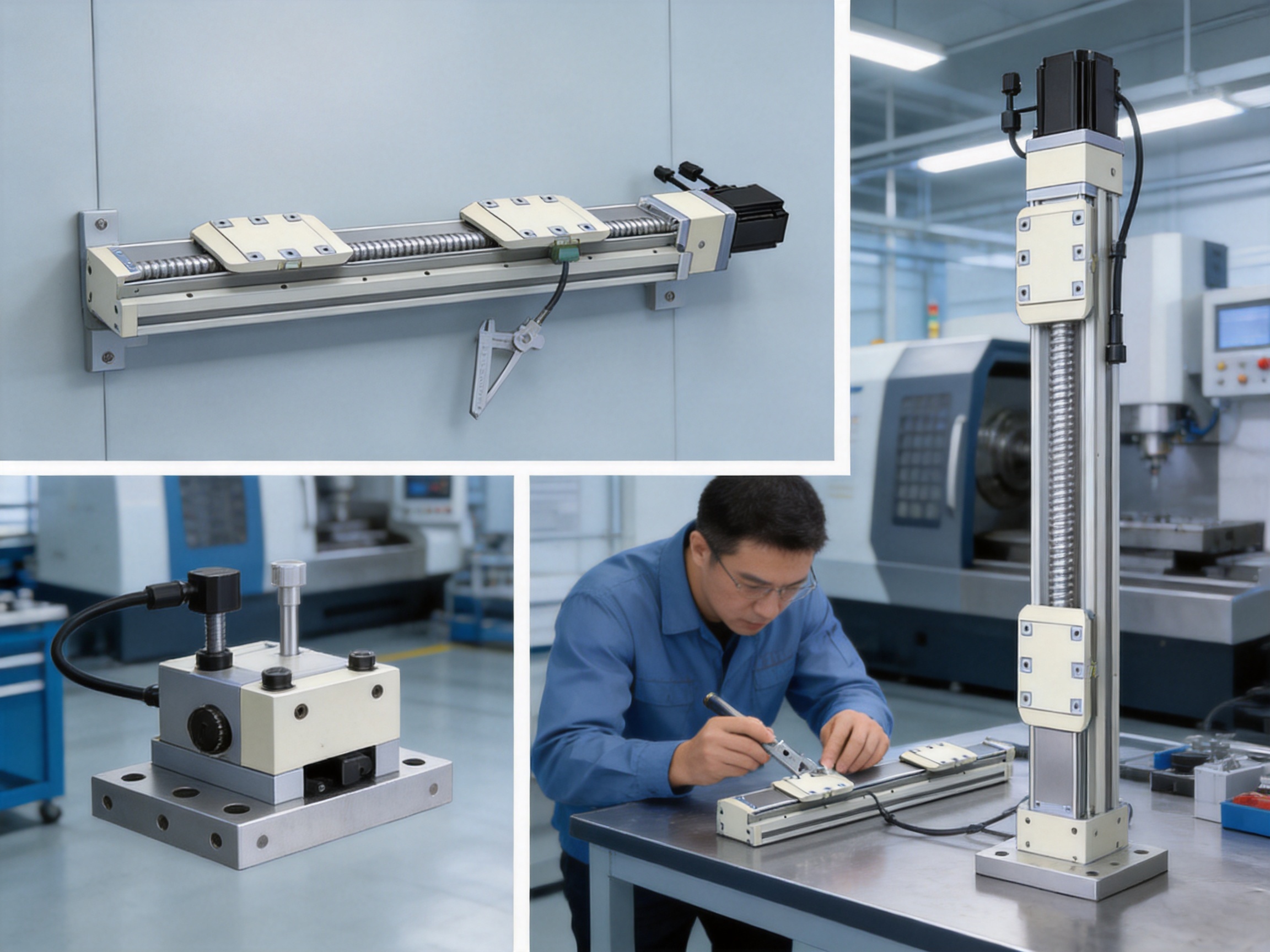
Compared with a conventional single-slider module, the dual-slider product offers a more balanced support structure. This can be advantageous when the payload is wide, offset, or subject to changing moments. A single-slider module may still be suitable for compact centered loads, but applications involving two fixtures, large tooling plates, or eccentric grippers may benefit from the additional support points.
The dual-slider design may also improve the stability of the moving platform during repeated acceleration and deceleration. This can reduce the tendency of the tooling to rotate or oscillate, helping maintain process quality in applications that require consistent orientation.
Building an axis from a separate guide rail, ball screw, support bearings, housing, motor mount, and sensor system can provide design flexibility, but it also creates additional engineering and assembly work. Each component must be selected, machined, aligned, and tested individually.
An integrated module reduces this burden by combining the principal motion elements into one coordinated product. The customer can benefit from shorter development time, fewer alignment procedures, reduced component sourcing complexity, and a more predictable installation process.
This integrated approach can also reduce the risk of incompatibility between the guide and screw. When separate parts are selected without sufficient attention to stiffness, load distribution, and mounting geometry, the final axis may not achieve the expected performance.
Belt-driven modules can provide high speed and long travel, but they may not be the best choice for every precision task. A ball screw module generally offers stronger thrust capability and is often preferred when the application requires controlled force, fine positioning, or resistance to load changes.
The Dual-Slider High-Precision Rail-Embedded Linear Module is therefore well positioned for tasks where repeatable positioning and mechanical stiffness are more important than maximum travel speed. Its maximum speed of 250 mm/s is appropriate for many industrial transfer and positioning operations, while the 5 mm lead supports useful thrust and controlled movement.
Some linear modules are designed around one proprietary motor or one fixed drive ecosystem. This can limit customer choice and increase the cost of standardization when a factory already uses another servo brand.
The availability of Mitsubishi, Panasonic, and Delta motor and driver options provides more flexibility. Customers can align the module with their existing servo inventory, control platform, maintenance procedures, and spare-parts strategy. Both brake and no-brake versions are available for different installation requirements.
Electronic manufacturing often requires clean, repeatable, and accurately controlled movement. The module can be used for circuit board transfer, component positioning, connector insertion support, inspection movement, dispensing alignment, and automated testing.
The dual-slider platform is useful when a fixture must remain level while moving through several stations. It can also support parallel handling of two workpieces or provide stable movement for a camera and lighting assembly.
Precision instruments often contain small, high-value components that must be aligned carefully. The module’s repeatability and stable guide structure can support screwdriving, probing, optical alignment, component loading, and calibration operations.
In these applications, the machine designer should minimize vibration, use a rigid base, and carefully tune acceleration and deceleration. The module can provide the mechanical foundation, but the final process performance depends on the complete machine.
Automated testing systems may require a probe, camera, sensor, or test fixture to move repeatedly between multiple positions. The product’s stroke options from 25 mm to 450 mm allow designers to select a travel length suited to compact or moderately extended test layouts.
The home sensor supports repeatable initialization, while the servo motor enables programmable speed and position profiles. The dual-slider arrangement can help keep the test fixture stable when the probe or sensor is mounted with an offset.
Parallel handling systems use more than one gripping or positioning point to improve throughput. Two sliders can support two fixtures, two grippers, or a long handling platform. Depending on the control configuration, the carriages can be operated together or used as separate positioning elements.
Potential applications include loading and unloading, tray handling, workpiece sorting, production-line transfer, and dual-station feeding. The correct synchronization method should be confirmed during system design to ensure that the mechanical arrangement and control logic are compatible.
The module can serve as a linear axis for robotic subassemblies, pick-and-place equipment, machine tending systems, and special-purpose machinery. It may be installed horizontally, vertically, or on a wall depending on the motion path.
When combined with rotary axes, electric cylinders, servo presses, or multi-axis platforms, the linear module can become part of a larger coordinated automation system. Its standardized servo interface and sensor options help simplify integration with industrial motion controllers.
The guaranteed service life is 10,000 km when the module is used normally and in compliance with the catalog specifications. This service-life statement depends on correct installation, appropriate lubrication, suitable loading, proper alignment, and operation within the specified speed, payload, moment, and environmental conditions.
Routine maintenance should include inspection of the guide and screw area, checking for contamination, verifying lubrication, examining fasteners, and observing the axis for unusual noise or changes in movement resistance. Cables and sensor wiring should also be inspected for fatigue, abrasion, and excessive bending.
Lubrication intervals should be determined according to duty cycle, operating speed, load, environment, and manufacturer recommendations. Dust, metal particles, moisture, and chemical exposure can shorten component life. Protective covers or machine enclosures may be needed in environments where contamination is likely.
Unexpected changes in repeatability, increased noise, abnormal vibration, rising motor temperature, or irregular servo load may indicate alignment problems, worn components, inadequate lubrication, or a changing external load. Early diagnosis can prevent secondary damage and reduce unplanned downtime.
The mounting base should be sufficiently rigid, flat, and stable across the entire module length. A flexible base can introduce deflection and misalignment even when the module has been manufactured correctly. The supporting frame should also resist vibration from other machine components.
Mounting holes, fasteners, and tool access should be checked before installation. The 50 mm stroke configuration requires particular attention because the slider may block top-locking mounting holes. Bottom-locking mounting holes should be used as recommended for that configuration.
The payload should be positioned as close as practical to the intended center of gravity and support area. Large offsets should be included in moment calculations. Tooling brackets should be designed to minimize unnecessary cantilevering and twisting.
The two sliders should not be forced into an uneven mechanical relationship by an inaccurately machined external platform. The attached fixture should be manufactured with suitable flatness and mounting accuracy so that it does not preload or distort the moving blocks.
Servo tuning should begin with conservative acceleration, deceleration, and speed settings. The engineer should verify direction, travel limits, home sensor operation, emergency stop behavior, and position feedback before introducing the full payload.
Acceleration should be increased gradually while monitoring vibration, following error, motor load, and mechanical noise. A stable mechanical installation makes servo tuning easier and helps the system achieve the specified repeatability in practical operation.
For vertical installations, the brake function must be checked under the actual load. The control system should be configured so that the brake is applied and released in the correct sequence. Safety measures should prevent unintended descent during maintenance, power loss, or control faults.
The machine risk assessment should determine whether additional mechanical support, counterbalance, guarding, or safety-rated stopping functions are required. The module should never be selected for a vertical load solely on the basis of motor power.
| Item | Specification | Application Significance |
| Module type | Dual-slider rail-embedded linear module | Provides distributed support and integrated guidance |
| Repeatability | ±0.01 mm | Supports repeatable positioning tasks |
| Ball screw lead | 5 mm | Balances thrust and positioning control |
| Maximum speed | 250 mm/s | Suitable for controlled industrial transfer |
| Horizontal payload | Up to 50 kg, dual carriage | Supports heavier horizontal fixtures and tooling |
| Vertical payload | Up to 15 kg, dual carriage | Suitable for selected lifting and vertical positioning tasks |
| Rated thrust | 1,388 N | Provides useful linear force for movement and positioning |
| Stroke range | 25–450 mm in 25 mm intervals | Offers standardized travel selection |
| Ball screw | C7, 16 mm diameter | Industrial-grade precision transmission |
| Servo output | 400 W AC servo | Enables programmable motion control |
| Coupling | 10 × 14 mm | Defines the motor connection interface |
| Home sensor | EE-SX674 NPN or FC-SPX307Z-2M NPN | Supports repeatable reference positioning |
| Static moment MY | 318 N·m | Reference limit for one tipping direction |
| Static moment MP | 318 N·m | Reference limit for another tipping direction |
| Static moment MR | 626 N·m | Reference limit for rotational loading |
| Design service life | 10,000 km under specified conditions | Supports long-term industrial use when properly maintained |
The first selection factor is the required stroke. The module is available from 25 mm to 450 mm in 25 mm increments. Designers should choose a stroke that provides the necessary working travel while avoiding unnecessary length, weight, and unsupported extension.
The second factor is installation orientation. Horizontal, wall-mounted, and vertical installations have different payload and overhang conditions. Vertical systems may require brake-equipped motors and additional safety provisions.
The third factor is payload geometry. Total mass alone is not enough. The designer should identify the center of gravity, the distance from the guide centerline, the width of the fixture, and the forces generated during acceleration and stopping.
The fourth factor is motor orientation. Right-side, left-side, exposed, and bottom-side motor arrangements allow the module to fit different machine layouts. Cable routing, maintenance access, adjacent mechanisms, and safety guarding should all be considered.
The fifth factor is the servo ecosystem. Mitsubishi, Panasonic, and Delta options can be selected according to the customer’s existing control architecture. Motor brake requirements should be established at the beginning of the design process, not after the axis has been installed.
The sixth factor is sensor and control compatibility. The NPN home sensor must be compatible with the controller input circuit. The machine designer should also define the home position, limit strategy, emergency stop behavior, and recovery procedure.
Working with an integrated motion manufacturer can provide advantages beyond the purchase of a single mechanical component. The manufacturer can support product selection, motor matching, sensor configuration, structural design, servo integration, and application evaluation.
This approach is especially valuable when the customer is developing a new machine or modifying an existing platform. Instead of coordinating separate suppliers for the module body, motor, driver, sensor, and control system, the customer can obtain a more coordinated solution from one engineering source.
The manufacturer’s experience across electric cylinders, linear modules, servo presses, robotic axes, and multi-degree-of-freedom platforms also supports more complex automation projects. The same technical team may be able to recommend a linear module for transfer, an electric cylinder for a force application, or a servo press for controlled assembly.
Research cooperation with industrial organizations and universities further strengthens the company’s ability to respond to specialized motion requirements. This combination of product manufacturing, engineering development, and application knowledge is useful for customers seeking customized or semi-standard automation solutions.
The two sliders distribute the load over two support points, improving load-bearing uniformity and movement stability. This is particularly useful for wide fixtures, eccentric loads, long tooling plates, and applications where the center of gravity is offset from the guide centerline.
The dual-slider design allows synchronized or independent operation in suitable system configurations. The exact independent-control capability depends on the selected mechanical and servo arrangement, so it should be confirmed during technical specification and quotation.
The maximum horizontal payload is specified as 50 kg with the dual carriage. The actual allowable load must also consider overhang, center of gravity, acceleration, speed, installation quality, and static moment limits.
The maximum vertical payload is specified as 15 kg with the dual carriage. Vertical applications should normally use a brake-equipped servo motor and appropriate safety measures to prevent unintended movement or descent.
Standard strokes range from 25 mm to 450 mm in 25 mm increments. The correct stroke should provide the required working travel without adding unnecessary module length or mass.
The specified repeatability is ±0.01 mm. Practical system performance also depends on servo tuning, mounting rigidity, load variation, temperature, lubrication, and the accuracy requirements of the complete machine.
The module uses a ball screw with a 5 mm lead and a C7 screw with a 16 mm diameter. This configuration supports controlled movement, useful thrust, and repeatable positioning.
Listed motor options include Mitsubishi, Panasonic, and Delta 400 W AC servo systems. Both brake and no-brake versions are available for different horizontal and vertical application requirements.
The standard specifications do not apply to ceiling-mounted inverted use. Such installations should be reviewed with the supplier because lubrication, load paths, mounting, and safety conditions may differ from standard orientations.
For the 50 mm stroke configuration, the slider may block the top-locking mounting holes on the main body. Only four screws may be available through that mounting arrangement, so bottom-locking mounting holes are recommended for securing the main body.
The guaranteed service life is 10,000 km when the module is operated normally and within the catalog specifications. Correct lubrication, alignment, load selection, cleanliness, and maintenance are necessary to achieve the stated service-life condition.
Suitable applications include electronic manufacturing, precision instrument assembly, automated testing, parallel handling, precision alignment, workpiece transfer, inspection equipment, robotic subassemblies, and special-purpose automation machinery.
The Dual-Slider High-Precision Rail-Embedded Linear Module provides a balanced combination of precision, load stability, compact integration, and configuration flexibility. Its two sliding blocks improve load distribution and support applications involving eccentric or widely distributed loads. The embedded high-precision rail contributes to a stable motion path, while the 5 mm lead ball screw supplies useful thrust and controlled positioning.
With ±0.01 mm repeatability, a maximum speed of 250 mm/s, a rated thrust of 1,388 N, strokes from 25 mm to 450 mm, and a horizontal dual-carriage payload of up to 50 kg, the module addresses a broad range of industrial automation requirements. Motor options from Mitsubishi, Panasonic, and Delta make it easier to align the axis with established customer control platforms.
The product’s competitive value comes not only from its specification sheet but also from its integrated design and manufacturing foundation. Advanced design software, high-precision CNC machining centers, an experienced R&D team, core patents, and cooperation with industrial and academic organizations support the development of reliable motion products.
For machine builders that require stable, repeatable, and space-efficient linear movement, this dual-slider rail-embedded structure can provide a strong alternative to single-slider modules and separately assembled guide-and-screw systems. Proper selection, installation, servo tuning, and maintenance remain essential, but when applied within its specified conditions, the module offers a practical foundation for precision automation and intelligent manufacturing equipment.
1. Product specification data for the Dual-Slider High-Precision Rail-Embedded Linear Module, including payload, speed, repeatability, stroke, motor, sensor, moment, and dimensional information.
2. Manufacturer technical information concerning electric cylinders, linear motion modules, linear motor modules, servo presses, robotic axes, and multi-degree-of-freedom motion platforms.
3. General industrial design principles for ball screw positioning systems, linear guideways, servo motor selection, and automated machine integration.
4. General engineering practices for payload calculation, overhang evaluation, static moment analysis, vertical-axis safety, and preventive maintenance of linear motion equipment.
5. General application guidance for precision automation in electronic manufacturing, instrument assembly, automated inspection, and industrial testing systems.
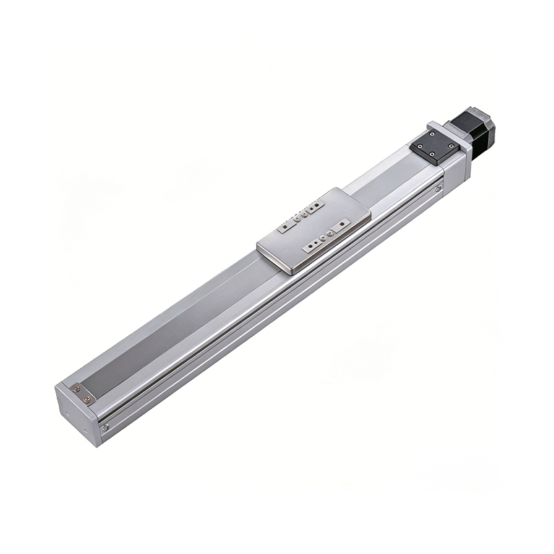 0.01mm High Precision Ball Screw Driven Rail-Embedded Linear Module
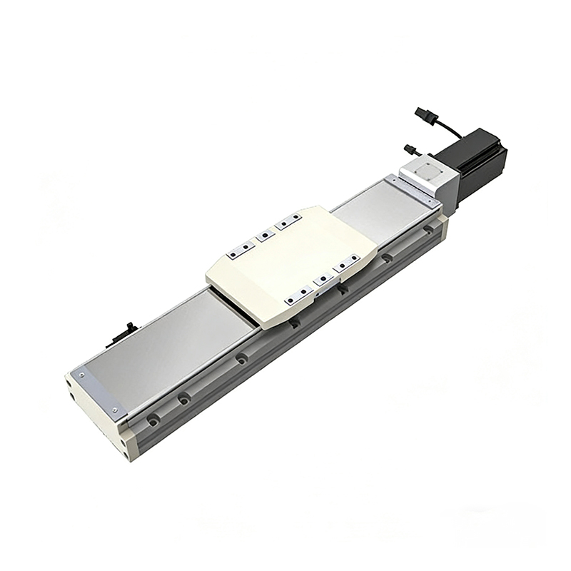 Heavy Load Ball Screw Driven Rail-Embedded Linear Module
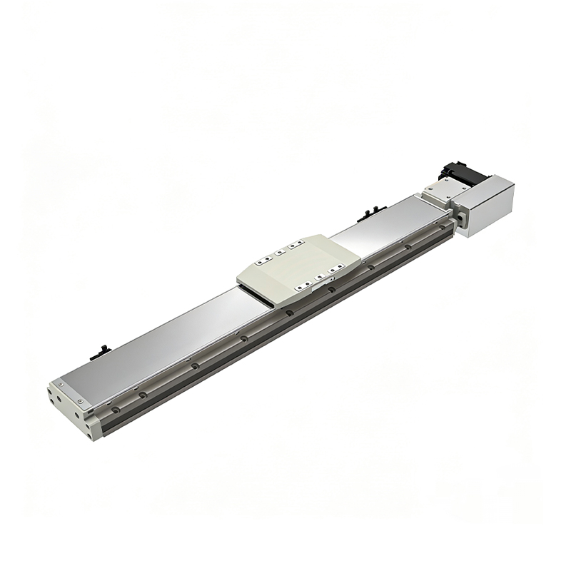 110KG Load Long Stroke Rail-Embedded Linear Module
Dual-Slider High Precision Rail-Embedded Linear Module
110KG Load Long Stroke Rail-Embedded Linear Module
Dual-Slider High Precision Rail-Embedded Linear Module
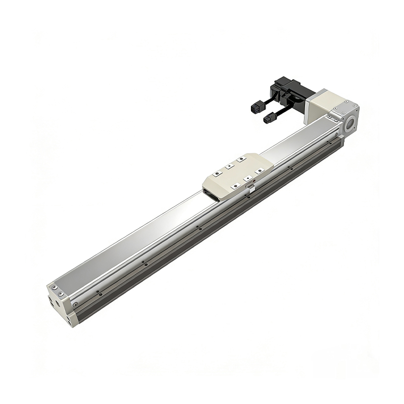 Belt Driven Dust-Proof Rail-Embedded Linear Module
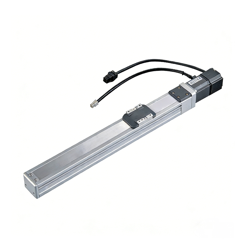 0.01mm High Precision Light Load Ball Screw Linear Module
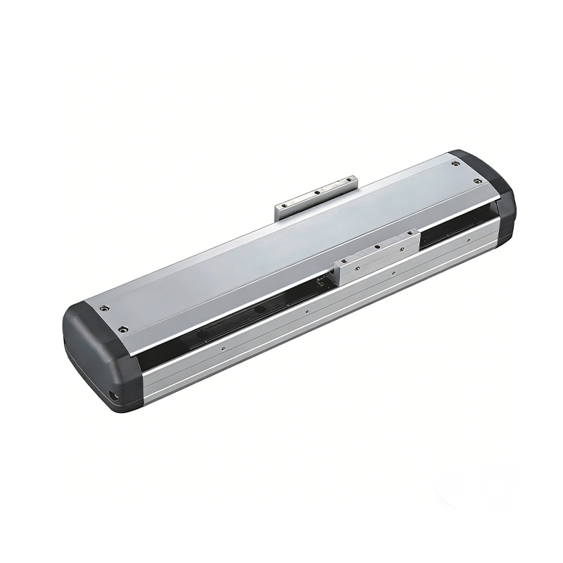 Ball Screw Linear Module with Built-in Sensor
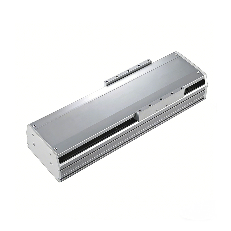 2000mm Long Stroke Ball Screw Linear Module
This 2000mm Long Stroke Ball Screw Linear Module is customized for large-range linear movement automation tasks, support...
READ MOREThis 2000mm Long Stroke Ball Screw Linear Module is customized for large-range linear movement automation tasks, support...
READ MOREThis 2000mm Long Stroke Ball Screw Linear Module is customized for large-range linear movement automation tasks, support...
READ MOREThis 2000mm Long Stroke Ball Screw Linear Module is customized for large-range linear movement automation tasks, support...
READ MORE
If you are interested in our products, please leave us a message. We look forward to providing you with
professional services!
Innovation and transcendence make factory intelligent manufacturing efficient and convenient!
+86 186 2508 0683
19962977901
sales@sz-tys.com
Building 5, Suzhou Mudu International Science and Technology Innovation Park, Jinfeng South Road, Suzhou City, Jiangsu Province, China
