


 English
 Français
 русский
 عربى
عربى Español
 Deutsch
Tel
+86 186 2508 0683

Modern manufacturing increasingly depends on equipment that can apply force accurately, record every critical process value, and make reliable quality decisions without slowing production. A desktop servo press machine answers this need by combining a compact mechanical structure with closed-loop servo control, programmable motion, force and displacement monitoring, and automatic quality judgment. Unlike a conventional mechanical press that generally relies on fixed stroke positions, cams, or manually adjusted pressure settings, a servo press can coordinate speed, position, force, dwell time, and return motion according to the requirements of each application.
The desktop servo press machine described in this article is designed as a high-precision benchtop pressing solution for laboratories, product development, small-batch manufacturing, and specialized assembly lines. Its compact footprint makes it suitable for work areas where a large industrial press would be impractical, while its available pressure range allows users to select a model matched to the process. The product family covers pressing capacities from 1 kN to 300 kN, with configurable travel, speed, pressure-maintaining time, and process-monitoring functions.
Its principal applications include press-fit assembly, punching, riveting, powder compacting, sealing, spring testing, stamping, forming, and other operations that require controlled force and displacement. The machine is also suitable for applications where the relationship between force and displacement is an essential indicator of product quality. By capturing this relationship during each cycle, manufacturers can identify incomplete insertion, excessive resistance, material fracture, insufficient compression, incorrect component positioning, and other process abnormalities.
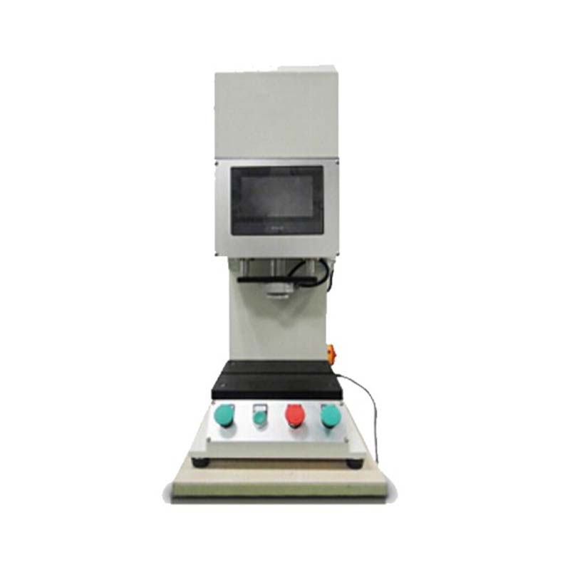
Desktop Servo Press Machine High Precision Benchtop Press
A desktop servo press machine is an electrically driven pressing system that uses a servo motor, transmission mechanism, force-sensing equipment, position feedback, and control software to manage the complete pressing cycle. The term “desktop” or “benchtop” refers primarily to the machine’s compact installation concept. It can be placed on a workbench, production table, laboratory stand, or dedicated support frame, depending on the selected capacity and application configuration.
The machine does not simply move a tool from one position to another. It creates a controlled process profile. The operator or process engineer can define an approach movement, a pressing speed, a target position or force, a pressure-maintaining period, and a return sequence. During operation, sensors provide feedback to the controller, allowing the system to compare actual values with programmed limits.
This closed-loop structure is important for precision assembly. In a press-fit operation, for example, the system can move rapidly toward the workpiece, reduce speed before contact, apply the required pressing force, stop at a specified position, and maintain pressure for a defined period. If the force rises too quickly or the final displacement is outside the permitted range, the controller can classify the result as NG, meaning not good. If the measured force and displacement remain within the configured process window, the result can be classified as OK.
Traditional presses may still be suitable for repetitive operations with very simple requirements, but they often provide limited information about what happened during the cycle. A servo press produces a traceable force-displacement record and supports more flexible process adjustment. This makes it valuable for products with narrow tolerances, expensive components, safety-related assemblies, or frequent model changes.
The compact design is one of the most practical advantages of a desktop servo press. Laboratories and small assembly cells often have limited floor area. A full-size hydraulic or mechanical press may require a large foundation, extensive guarding, auxiliary power equipment, and a dedicated operating zone. A benchtop servo press can be integrated into a smaller workstation while still providing controlled pressing performance.
A smaller footprint also makes it easier to relocate the equipment between development areas, inspection stations, and production cells. This flexibility supports pilot production, engineering validation, and small-batch manufacturing. For companies that produce several product variants, a compact machine can be assigned to a specific process or moved when production priorities change.
The most significant performance benefit is closed-loop control. The controller continuously receives feedback from the force and position systems and uses this information to regulate the movement of the pressing axis. This allows the machine to achieve repeatable pressure application and accurate stopping positions.
Force control is essential when the workpiece has a defined strength limit or when the assembly must reach a specific compression level. Displacement control is important when the final position determines the functional performance of the product. Combining both values allows the machine to detect process conditions that might remain hidden if only force or only position were monitored.
For instance, a component may reach the programmed force before reaching the correct insertion depth because of an obstruction or dimensional variation. In another case, the component may reach the specified position with unusually low resistance, indicating a missing part or poor fit. A force-displacement evaluation can distinguish these conditions and prevent defective products from being passed to the next operation.
The technical data specifies a pressure setting unit of 1 N and a displacement setting unit of 0.01 mm. Speed can also be configured in increments of 0.01 mm/s. These setting resolutions give process engineers a fine adjustment capability during trial production and optimization.
Fine setting resolution does not mean that every process will achieve the same absolute accuracy under all conditions. Actual performance depends on tooling, sensor calibration, workpiece tolerances, machine installation, temperature, and application design. Nevertheless, the ability to establish detailed control parameters provides a strong foundation for repeatable process development.
Automatic judgment reduces reliance on subjective operator inspection. The system can evaluate force, position, speed, pressure-maintaining behavior, and other programmed conditions. A result that falls inside the defined process window is marked OK, while a result outside the permitted limits is marked NG.
This function supports consistent quality decisions across operators and shifts. It also helps reduce the risk that a defective part will be overlooked during a high-volume or repetitive operation. In applications involving press-fit assemblies, sealing, riveting, and spring testing, automatic judgment can be particularly valuable because visual inspection alone may not reveal an internal process defect.
The human-machine interface provides a central point for operating the equipment, setting process parameters, and monitoring production information. A clear HMI allows operators to observe the current force, displacement, motion status, cycle result, and alarm information. Process engineers can use the interface to adjust profiles and review the relationship between force and displacement.
Real-time monitoring is also useful during commissioning. When a new tool or product is introduced, engineers can observe the process curve and identify whether the pressing speed, contact point, target force, and final position are appropriate. This shortens the time required to stabilize a new application.
Electrical servo drive technology can provide lower operating noise than many conventional hydraulic systems because it does not require a continuously running hydraulic pump. Energy is used primarily when the axis is moving or maintaining the required process condition. This can help reduce energy waste during idle periods, particularly in laboratories and small production cells.
Lower noise contributes to a more comfortable working environment. It is especially important in inspection rooms, research laboratories, training facilities, and assembly areas where several machines operate close to one another. Energy efficiency also supports manufacturers seeking to reduce operating costs and improve the environmental performance of their production equipment.
Press-fit assembly is one of the most important applications for a servo press. Components such as bearings, bushings, pins, housings, connectors, and electronic parts often require a controlled insertion force and a defined final position. Excessive force may damage the parts, while insufficient force may create a loose or unreliable assembly.
A controlled servo press can perform the approach, contact detection, insertion, stopping, and return sequence automatically. By recording the force-displacement curve, the machine can help confirm that the component was installed correctly. The supplied application record indicates more than 200 press-fit assembly projects and a first-pass yield of 99.2 percent for supported applications. Such figures illustrate the value of process monitoring when the application is properly engineered and the tooling is correctly matched.
For punching and light stamping, controlled movement can help maintain consistent tool engagement and reduce process variation. The press can be programmed with a suitable approach speed, forming speed, stopping position, and return profile. Force monitoring can identify abnormal material resistance, misalignment, tool wear, or an improperly positioned workpiece.
The product information cites more than 150 punching applications, with hole diameter tolerance controlled within ±0.05 mm in relevant projects. Actual tolerance depends on material, die design, clearance, tool condition, fixture rigidity, and machine setup. However, the servo press’s ability to regulate motion and monitor the pressing process provides a more controlled foundation than a simple fixed-stroke mechanism.
Riveting requires enough force to form a secure joint without cracking the rivet, deforming the workpiece, or damaging nearby components. The appropriate force profile can vary according to rivet material, diameter, length, and workpiece construction.
A servo press can be configured to control the forming stroke and monitor the force required during riveting. Abnormal force patterns may indicate a missing rivet, incorrect material, misalignment, or an improperly prepared hole. The supplied information reports more than 200 riveting projects and a riveting strength compliance rate above 98 percent in applicable work. This demonstrates how controlled pressing and process verification can improve joint consistency.
Powder compacting requires controlled compression and repeatable forming conditions. The material must be compressed to the desired shape and density without creating cracks, delamination, or excessive variation. A servo-controlled press can regulate the compression stage and maintain pressure for a defined duration.
The pressure-maintaining function is specified up to a maximum of 3,000 seconds. Such a wide setting range gives engineers the flexibility to develop processes that require a brief holding period or an extended dwell. The available data also cites more than 300 powder compacting cases and forming precision of ±0.02 mm in supported applications. As with all forming processes, results depend on powder characteristics, mold design, lubrication, density distribution, and environmental conditions.
Sealing applications often require a specific compression level rather than simply maximum force. A seal that is under-compressed may leak, while excessive compression can damage the seal or reduce service life. The servo press can apply a defined force or travel, maintain the condition, and evaluate the completed cycle.
Force and displacement records can help identify a missing seal, incorrect seal hardness, improper groove dimensions, or contamination between mating surfaces. The supplied project summary refers to more than 500 sealing solutions and a leakage rate as low as 0.1 percent in relevant applications. These results depend on complete system engineering, including seal material, fixture design, testing method, and product tolerances.
Springs must often be evaluated at one or more specified heights to determine load, rate, compression behavior, and recovery. A servo press provides a controlled movement and measures the force at a defined displacement. This makes it suitable for compression spring testing, elastic component verification, and incoming quality inspection.
The equipment can be used to check whether the spring reaches the required load at a particular height or whether the measured force remains within a permitted range. Because the machine records the relationship between force and displacement, it can provide more meaningful information than a simple pass/fail gauge.
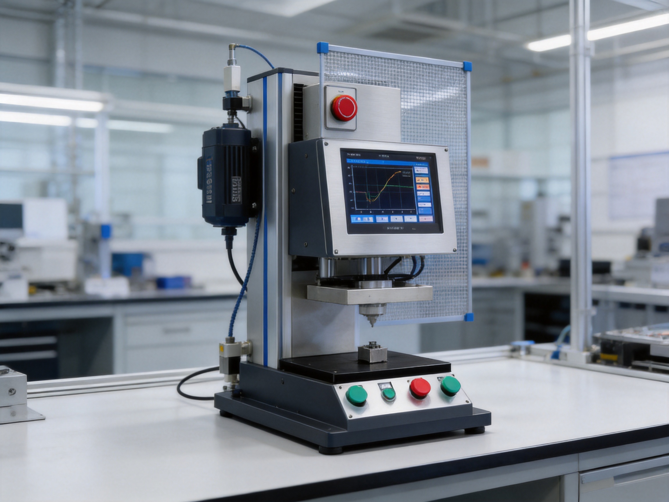
Force-displacement monitoring is the foundation of reliable process verification. During a pressing cycle, the machine can create a curve showing how force changes as the pressing axis moves. This curve can be compared with a reference profile or with upper and lower control limits.
A normal press-fit operation may show a predictable contact point followed by a gradual increase in force and a stable final position. A sudden force spike could indicate a burr, obstruction, incorrect orientation, or tool misalignment. A curve with unusually low force could indicate that a component is missing, undersized, or not engaged properly. A displacement that stops too early may signal a blocked path or an incorrect part height.
For riveting, the curve can reveal whether the rivet formed correctly. For sealing, it can show whether the material compressed as expected. For spring testing, it can provide a complete load-versus-height profile. For powder compacting, the curve can support analysis of forming resistance and compression stability.
This data can be used at several levels. At the operator level, it provides immediate OK/NG feedback. At the engineering level, it supports parameter optimization and root-cause analysis. At the quality level, it creates evidence that the process was performed within defined limits. At the management level, it can support yield improvement, maintenance planning, and continuous production improvement.
The servo press family covers pressure capacities from TYSP-01 at 1 kN to TYSP-300 at 300 kN. This broad range allows the machine concept to be applied to delicate laboratory operations as well as more demanding industrial forming and assembly tasks.
| Model | Maximum Pressure | Maximum Trip | Press-Fit Speed | Fast Forward/Return Speed | Pressure Maintaining |
| TYSP-01 | 1 kN | 200 mm | 0–35 mm/s | 0–100 mm/s | 0–3000 s |
| TYSP-05 | 5 kN | 200 mm | 0–35 mm/s | 0–100 mm/s | 0–3000 s |
| TYSP-10 | 10 kN | 200 mm | 0–35 mm/s | 0–100 mm/s | 0–3000 s |
| TYSP-20 | 20 kN | 200 mm | 0–35 mm/s | 0–100 mm/s | 0–3000 s |
| TYSP-30 | 30 kN | 250 mm | 0–35 mm/s | 0–100 mm/s | 0–3000 s |
| TYSP-50 | 50 kN | 350 mm | 0–35 mm/s | 0–100 mm/s | 0–3000 s |
| TYSP-70 | 70 kN | 350 mm | 0–35 mm/s | 0–100 mm/s | 0–3000 s |
| TYSP-100 | 100 kN | 500 mm | 0–35 mm/s | 0–100 mm/s | 0–3000 s |
| TYSP-150 | 150 kN | 500 mm | 0–30 mm/s | 0–50 mm/s | 0–3000 s |
| TYSP-200 | 200 kN | 500 mm | 0–25 mm/s | 0–50 mm/s | 0–3000 s |
| TYSP-250 | 250 kN | 500 mm | 0–20 mm/s | 0–50 mm/s | 0–3000 s |
| TYSP-300 | 300 kN | 500 mm | 0–15 mm/s | 0–30 mm/s | 0–3000 s |
Capacity selection should begin with the actual process requirement rather than the maximum available machine force. Engineers should determine the normal pressing force, expected variation, emergency load, tool stiffness, workpiece strength, required stroke, and cycle time. Selecting a machine with adequate reserve capacity can improve reliability, but excessive capacity may increase cost, structure size, and energy consumption without providing a practical benefit.
The maximum pressure range and allowed operating band are also important. The listed models provide an allowed band corresponding to approximately 10 percent to 100 percent of the maximum pressure value. For example, the 10 kN model has an indicated operating band from 1 kN to 10 kN, while the 100 kN model has an indicated band from 10 kN to 100 kN. The minimum detection value is specified as 0.2 percent of the maximum pressure value.
The pressure setting unit is 1 N across the listed models. This allows small parameter adjustments during process development. The maximum travel ranges from 200 mm on the lower-capacity models to 500 mm on several higher-capacity models. The setting unit for travel is 0.01 mm.
Press-fit speed varies by model. The smaller models provide a range up to 35 mm/s, while higher-capacity models provide lower maximum pressing speeds because of their greater force capability and mechanical requirements. Fast forward and return movement can reach 100 mm/s on many models, while the largest models use lower speed ranges of 30 mm/s or 50 mm/s.
The distinction between press-fit speed and fast forward or return speed is useful for cycle-time optimization. The machine can approach the workpiece quickly, slow down for contact and pressing, and return efficiently after the process is complete. This avoids using a slow working speed for the entire stroke and can improve productivity while preserving process control.
| Specification Item | Setting or Maximum Value | Unit |
| Pressure setting unit | 1 | N |
| Minimum detection value | 0.2% of maximum pressure value | Pressure reference |
| Travel setting unit | 0.01 | mm |
| Speed setting unit | 0.01 | mm/s |
| Maximum pressure-maintaining time | 3000 | s |
| Maximum travel | 200–500 depending on model | mm |
| Press-fit speed | 0–15 to 0–35 depending on model | mm/s |
| Fast forward/return speed | 0–30 to 0–100 depending on model | mm/s |
A servo press must provide sufficient rigidity to resist deformation during force application. The frame, guide system, drive assembly, tooling interface, and work support all influence the final pressing result. A rigid structure helps maintain alignment between the upper tool and the workpiece and reduces unwanted deflection during the cycle.
The dimensional information supplied for the product family includes different values for diameter, working dimensions, and overall machine dimensions. Representative models include TYSP-05 and TYSP-10 with a 200 mm lead, 108 mm diameter, 285 mm stroke-related dimension, and 380 mm length-related dimension. The listed overall heights are approximately 1,880 mm for several configurations, while larger models reach approximately 2,100 mm or 2,200 mm.
| Model | Lead | D | S | L2 | W2 | H2 | Overall L2 | Overall W1 | Overall H1 |
| TYSP-05 | 200 mm | 108 mm | 285 mm | 380 mm | 240 mm | 900 mm | 750 mm | 780 mm | 1880 mm |
| TYSP-10 | 200 mm | 108 mm | 285 mm | 380 mm | 300 mm | 900 mm | 750 mm | 780 mm | 1880 mm |
| TYSP-20 | 200 mm | 108 mm | 285 mm | 380 mm | 300 mm | 900 mm | 750 mm | 780 mm | 1950 mm |
| TYSP-30 | 200 mm | 208 mm | 385 mm | 580 mm | 400 mm | 900 mm | 800 mm | 950 mm | 1950 mm |
| TYSP-50 | 200 mm | 208 mm | 385 mm | 580 mm | 500 mm | 900 mm | 1000 mm | 1100 mm | 2100 mm |
| TYSP-70 | 200 mm | 308 mm | 385 mm | 580 mm | 550 mm | 900 mm | 1000 mm | 1100 mm | 2200 mm |
Because dimensional labels may vary according to a particular machine drawing or configuration, buyers should confirm the final outline drawing, worktable height, installation method, guarding requirements, tool clearance, and maintenance access before ordering. A compact machine still requires a stable support structure and sufficient space for safe loading, unloading, cable routing, and emergency access.
A conventional mechanical press is often optimized for a fixed motion profile. It may operate very efficiently when the same operation is repeated continuously, but changing the stroke, speed, dwell, or force behavior can require mechanical adjustments or tooling changes. A servo press changes many of these parameters through software and the HMI.
This flexibility is valuable for small-batch production and product families with different dimensions. Engineers can create separate process recipes for different workpieces, provided that the tooling and machine capacity are suitable. Recipe-based operation can also reduce setup errors by limiting manual parameter changes.
Hydraulic presses can deliver high force, but they commonly require pumps, hydraulic oil, hoses, valves, and routine checks for leakage or pressure stability. An electric servo press avoids the need for hydraulic fluid in the pressing drive and can offer a cleaner operating environment. It may also consume less energy during idle periods because the motor is not required to run continuously to maintain system pressure.
For laboratories and electronics-related assembly, the cleaner electrical architecture can be an important practical advantage. It reduces the risk of oil contamination near sensitive parts and simplifies routine housekeeping. The appropriate choice still depends on force, stroke, duty cycle, environmental conditions, and safety requirements.
Pneumatic presses are widely used for simple operations because of their straightforward design and relatively low initial cost. However, their output may vary with air pressure, cylinder friction, valve timing, and load conditions. Basic pneumatic systems may also lack high-resolution force and position feedback.
A servo press provides a more detailed view of the operation. The user can establish a defined force or position target and monitor actual behavior. This is particularly useful when quality depends on a narrow process window or when the workpiece is too valuable to accept uncontrolled force variation.
Quality records are becoming more important in electronics, automotive components, medical-related devices, energy equipment, and precision machinery. A servo press can support traceability by recording cycle results and process curves. Even when a complete factory data system is not installed, immediate OK/NG judgment and visible process information provide a higher level of control than manual pressing.
For manufacturers seeking to improve first-pass yield, the ability to analyze failed cycles is especially useful. Rather than treating every defect as an isolated event, engineers can compare curves, identify common patterns, and correct the underlying fixture, material, or parameter problem.
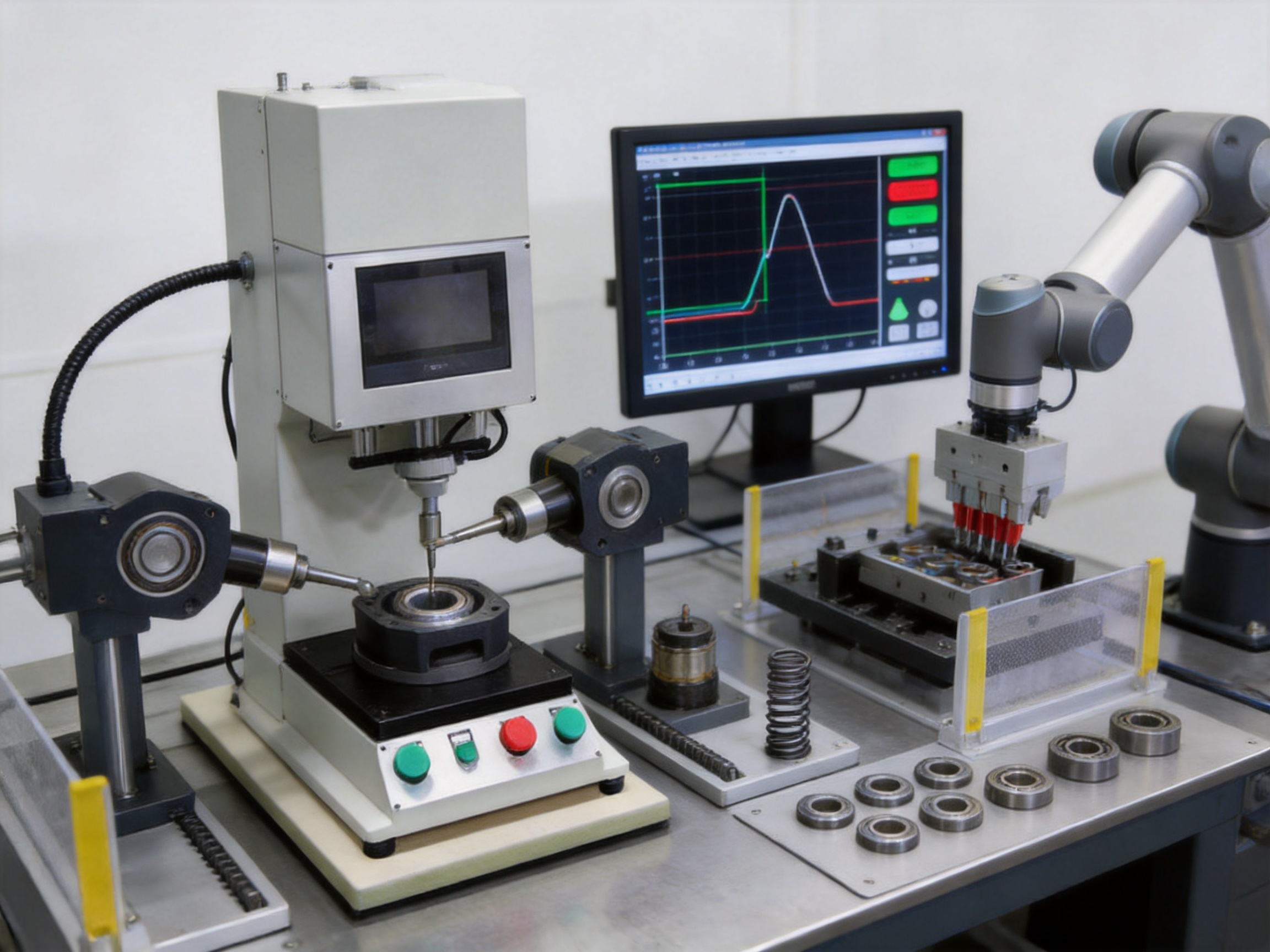
The performance of a servo press depends not only on the selected motor and controller but also on the quality of its design, machining, assembly, calibration, and testing. The manufacturer described in the supplied information integrates research and development, production, and sales. Its manufacturing capabilities include advanced design software and high-precision CNC machining centers.
Design software supports the development of mechanical structures, drive arrangements, tooling interfaces, and complete automation solutions. Engineers can evaluate dimensions, interference, assembly relationships, and structural requirements before production. This reduces design errors and helps align the machine with the customer’s workpiece and process conditions.
High-precision CNC machining centers are used to produce mechanical components with controlled dimensions and repeatable geometry. Accurate machining is essential for frame interfaces, guide mounting surfaces, tooling plates, transmission components, and other parts that influence alignment. Better machining consistency helps reduce assembly variation and supports the stable operation of the pressing axis.
The company also maintains a portfolio of core patents and has developed products in related fields, including electric cylinders, linear motion modules, linear motor modules, robotic seventh axes, six-degree-of-freedom platforms, algorithmic control software, and multi-degree-of-freedom linkage systems. This broader technical background can benefit servo press development because pressing equipment often requires coordinated knowledge of motion control, electromechanical design, sensing, software, and automation integration.
An integrated development and manufacturing structure can shorten the communication path between engineering and production. Design engineers can receive direct feedback from machinists, assembly personnel, commissioning teams, and application specialists. This feedback can improve manufacturability, serviceability, and process stability.
For customers, integrated capabilities may also simplify customization. A press application can require a special stroke, fixture, tool adapter, sensor arrangement, guarding system, or communication interface. A supplier with experience in electric cylinders and motion platforms can evaluate the pressing system as part of a larger automation solution rather than treating it as an isolated machine.
Application experience is a major differentiator in precision pressing. A machine can have strong nominal specifications, but successful implementation also requires correct tool design, workpiece support, force sensor placement, motion profile development, and acceptance criteria.
The supplied records refer to hundreds of application projects across press fitting, punching, riveting, powder compacting, and sealing. This type of experience can help engineers identify common failure modes before production begins. It can also reduce commissioning time by providing practical starting points for force limits, speed profiles, holding periods, and OK/NG windows.
The HMI is the operator’s primary interface with the servo press. A well-configured HMI should display the selected recipe, current operating mode, live force, position, speed, cycle status, alarm messages, and final judgment. It should also provide controlled access to parameter settings so that operators can run the process without accidentally changing engineering limits.
During setup, the operator can select the appropriate model recipe or product program, define the working stroke, establish the press-fit speed, configure the fast approach and return movement, and set the pressure-maintaining time. The process engineer can define upper and lower limits for force and displacement and determine the conditions that classify a cycle as OK or NG.
During automatic operation, the machine performs the programmed sequence and checks the feedback values. If a value exceeds its permitted range, the system can stop or complete the cycle according to the configured safety and process logic. The HMI can then display the result and alarm information for operator action.
Good HMI design is not only about convenience. It contributes to process security by separating routine operation from engineering adjustment. It also helps standardize work instructions, minimize setup mistakes, and make training easier for new operators.
Before selecting a model, identify the workpiece dimensions, material, mating components, required final position, maximum permitted force, target compression, expected cycle time, and acceptable variation. Determine whether the process should be controlled primarily by force, position, or a combination of both.
Choose a machine with sufficient pressure capacity and travel for the application. The nominal process force should not be placed unnecessarily close to the machine’s maximum value. Include a suitable reserve for material variation, tooling friction, and transient load. Confirm that the required tool height and working clearance fit within the selected structure.
Tooling must guide the components accurately and distribute force correctly. The fixture should support the workpiece without introducing distortion. Replaceable tool inserts may be useful for product families, while locating features can prevent incorrect orientation. The tool material and surface finish should be selected according to the workpiece and expected production volume.
Begin with a conservative approach speed and pressing speed. Use a fast forward movement only where the workpiece and tooling allow it. Reduce speed before contact if the operation is sensitive to impact. Set an appropriate maximum force and travel limit to protect both the machine and the product.
Collect data from qualified good parts and determine the normal force-displacement pattern. Set the OK window wide enough to accommodate normal variation but narrow enough to detect meaningful defects. Testing should include intentionally incorrect conditions, such as a missing part, reversed component, excessive interference, insufficient compression, or misalignment.
Run repeated cycles under normal operating conditions and review the results. Check whether the force and displacement values remain stable over time. Confirm the machine’s response to alarms and verify that NG products are clearly identified and isolated from acceptable products.
Preventive maintenance should include inspection of the frame, guide components, transmission system, tooling, electrical connections, sensors, and safety devices. The pressing tool should be checked for wear, damage, burrs, and contamination. A worn tool can change the force-displacement curve even when the machine itself remains correctly calibrated.
Force and position sensors should be checked according to the manufacturer’s recommended schedule and the customer’s quality system. Calibration records should be maintained for applications that require formal traceability. If the machine is used in a clean laboratory or electronics environment, dust and contamination control should also be included in routine maintenance.
Operators should monitor unusual noise, vibration, heating, positioning errors, or changes in cycle time. Early identification of these conditions can prevent unplanned downtime. The servo system’s diagnostic information can help maintenance personnel determine whether the problem relates to the motor, drive, feedback device, mechanical transmission, or process tooling.
Correct lubrication, fastening, alignment, and cable management are also essential. A well-designed machine can still lose performance if the worktable shifts, the tooling becomes loose, or cables are exposed to repeated bending beyond their intended range.
Although the machine is suitable for benchtop use, the servo press concept can also be incorporated into a larger automation cell. It can be combined with electric cylinders, linear motion modules, robotic handling systems, inspection equipment, feeding devices, and product tracking systems. A typical cell may load a component, verify its presence, perform the pressing cycle, read the OK/NG result, and transfer the finished product to the next station.
The manufacturer’s experience with linear motion products, robotic seventh axes, motion simulation platforms, and multi-degree-of-freedom systems provides a useful foundation for broader automation integration. This is valuable for customers who want one engineering partner for both the press and the surrounding motion system.
Integration planning should address communication protocols, input and output signals, safety circuits, recipe selection, product identification, alarm handling, and data storage. The machine should be installed so that operators can safely access the loading area while remaining protected from moving parts. The final guarding and risk assessment must be adapted to the application, tooling, force level, and local regulations.
Large production presses are not always economical for product development, laboratory testing, or low-volume manufacturing. A desktop servo press offers a more adaptable solution for these environments. Engineers can use it to evaluate assembly forces, verify new materials, compare component tolerances, and establish production parameters before transferring the process to a high-volume line.
Small-batch manufacturers benefit from programmable recipes and the ability to handle multiple products with different process requirements. Instead of building a separate dedicated mechanical system for every product, the same servo press can be reconfigured with suitable tooling and software parameters when the application permits.
The compact design also supports educational and research environments. Students and researchers can study force-controlled motion, mechanical forming, elastic behavior, and quality evaluation without requiring a large industrial installation. The real-time HMI display makes the relationship between motion and force easier to observe and analyze.
Suzhou Tongyousheng Electronic Technology Co., Ltd. was established in 2013 and operates as a high-tech enterprise integrating research and development, manufacturing, and sales. Its product portfolio covers electric cylinders, linear motion modules, linear motor modules, servo presses, robotic seventh axes, and six-degree-of-freedom motion platforms.
The company’s technical development includes algorithmic control software and multi-degree-of-freedom platform linkage systems. This indicates experience in both mechanical equipment and control-oriented product development. For servo press customers, such combined expertise can support the design of motion profiles, control logic, and integrated systems.
The company reports collaboration with state-owned enterprises, defense technology institutions, and leading universities. These relationships support cooperation between industry, academia, and research and can contribute to the development of specialized automation technologies. The company also emphasizes quality, reputation, innovation, and development as core values.
Its manufacturing environment includes advanced design tools and high-precision CNC machining centers. A structured production process generally includes design review, component machining, surface treatment where required, mechanical assembly, electrical installation, software configuration, calibration, application testing, and final inspection. Each stage contributes to the reliability of the completed servo press.
These strengths are relevant when customers require more than a standard catalog product. A precision press may need a special workholding arrangement, different tool interface, modified travel, customer-specific data monitoring, or integration with existing equipment. A supplier with an established R&D and production base is better positioned to evaluate such requirements systematically.
International buyers should provide detailed application information when requesting a quotation. Important information includes the workpiece drawing, material, target force, required displacement, cycle time, tool dimensions, expected daily cycles, accuracy requirements, installation environment, electrical standards, and desired automation level.
Buyers should also clarify whether they require a standalone benchtop machine, a complete workstation, safety guarding, a custom fixture, automatic loading, barcode or product identification, data export, or connection to a factory information system. Clear application information allows the supplier to recommend the correct model and avoid selecting a machine based only on maximum force.
Acceptance criteria should be agreed before production. These may include force accuracy, displacement repeatability, maximum cycle time, OK/NG judgment behavior, alarm response, data recording, and performance using customer-supplied tools and parts. Factory acceptance testing and site acceptance testing can then be conducted against documented requirements.
Training and service arrangements should also be considered. Operators need instruction in recipe selection, safe loading, basic troubleshooting, and daily inspection. Maintenance personnel need access to technical documentation, calibration procedures, replacement-part information, and service support.
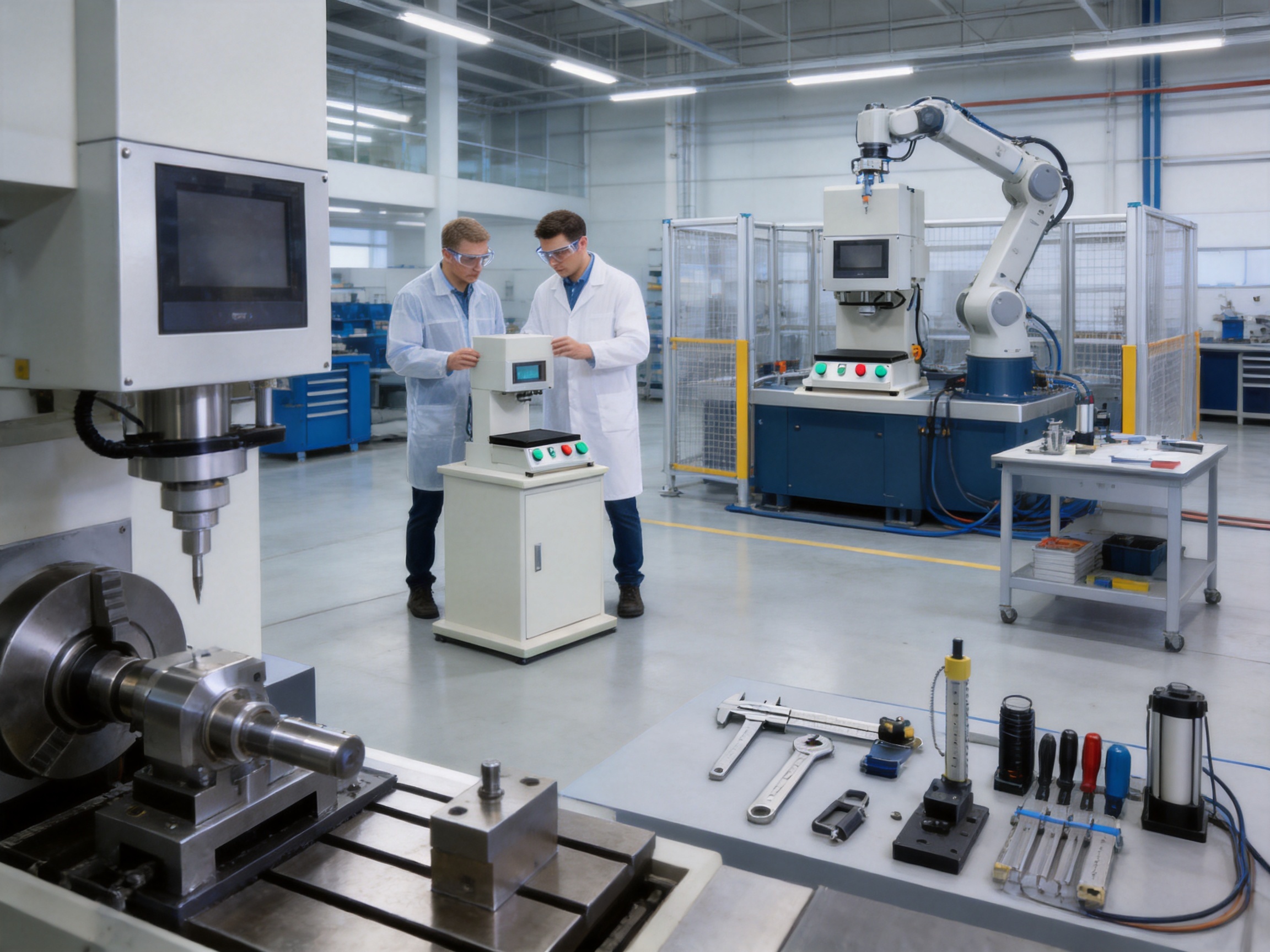
A servo press applies significant mechanical force and must be operated with appropriate safeguards. The final machine configuration should include risk assessment, suitable guarding, emergency stop functions, access control where necessary, and safe operating procedures. Tooling must be securely fixed, and operators should keep hands clear of the pressing zone.
Safety settings should include travel limits, force limits, and controlled recovery after an interruption. The machine should not be operated with damaged tools, loose fixtures, exposed electrical components, or bypassed safety devices. Any customer-specific automation must be evaluated as part of the complete machine system.
Safety requirements vary by country, industry, and application. Buyers should confirm applicable standards and ensure that the final installation complies with local regulations. The information in this article describes product capabilities and application principles; it does not replace a site-specific safety assessment or professional machine-risk evaluation.
Its main purpose is to perform controlled pressing, fitting, forming, testing, or joining operations using programmable force and displacement. It is suitable for precision assembly, laboratory work, small-batch production, and automated manufacturing cells.
A servo press uses closed-loop electrical motion control and can adjust speed, position, force, and holding time through software. A conventional mechanical press generally follows a fixed mechanical motion and may provide less process data. The servo press is therefore more flexible for variable products and quality-critical operations.
Yes. The machine can monitor force and displacement during the process and compare measured values with configured limits. It can then provide automatic OK/NG judgment. The exact inspection logic depends on the selected configuration and application requirements.
The listed product family includes models from 1 kN to 300 kN. The correct capacity should be selected according to the required process force, tooling design, workpiece strength, stroke, duty cycle, and safety margin.
Maximum travel varies by model. The listed range is from 200 mm on several smaller models to 500 mm on many higher-capacity models. The final value should be confirmed against the machine model and application drawing.
Applications include press-fit assembly, punching, riveting, powder compacting, sealing, spring testing, stamping, elastic testing, and precision forming. The machine is especially useful when process force and displacement must be monitored together.
The technical information lists a maximum pressure-maintaining time of 3,000 seconds. The suitable holding time depends on the material, product design, process objective, and required cycle time.
Yes. Its compact structure, low-noise electrical drive, programmable motion, and force-displacement monitoring make it suitable for connectors, motors, electronic assemblies, and other small precision components. Tooling and process parameters must be developed for the specific product.
Yes. The servo press can be designed as part of an automated cell with feeding, handling, inspection, tracking, and transfer equipment. Integration requirements should be defined during the technical review.
Provide the workpiece drawing, material, required force, target position, stroke, cycle time, product tolerance, tool dimensions, production volume, installation conditions, and desired data or automation functions. Sample parts and process descriptions are also helpful.
Regular maintenance should include inspection of tooling, guides, transmission parts, fasteners, cables, sensors, safety devices, and machine alignment. Force and position systems should be checked and calibrated according to the application’s quality requirements.
Yes. Even a benchtop machine must be installed on a stable, rigid, and level support surface. The support must accommodate the machine’s weight, operating force, vibration, working height, and safety access requirements.
The desktop servo press machine is a practical solution for manufacturers that need precision pressing without the size and fixed operating profile of conventional equipment. Closed-loop servo control enables accurate force and displacement management, while real-time monitoring and automatic OK/NG judgment improve process visibility and quality consistency.
Its compact design, low-noise electrical operation, energy-conscious performance, programmable speed, fine setting resolution, and broad capacity range make it suitable for laboratories, small-batch assembly, and demanding industrial applications. Press-fit assembly, punching, riveting, powder compacting, sealing, spring testing, and precision forming can all benefit from a machine that evaluates not only where the press stops but also how the force develops during the process.
The manufacturer’s strengths in R&D, high-precision CNC machining, motion control, electric cylinders, linear modules, servo systems, and multi-degree-of-freedom automation provide a broader technical foundation for customized solutions. Its application experience across hundreds of projects further supports process development and equipment selection.
For the best result, the machine should be selected as part of a complete process solution. Correct capacity, tooling, fixture rigidity, sensor configuration, motion profile, quality window, safety system, and maintenance plan are all essential. When these elements are engineered together, a desktop servo press can provide a repeatable, data-driven, and adaptable foundation for modern precision manufacturing.
1. Product specification materials for the TYSP series desktop servo press machine, including pressure range, travel, speed, and pressure-maintaining data.
2. Application summary for press-fit assembly, punching, riveting, powder compacting, sealing, and spring testing.
3. Manufacturer-provided information concerning research and development, CNC machining, automation products, patents, and manufacturing capabilities.
4. General principles of servo motion control, force-displacement monitoring, and programmable industrial pressing systems.
5. General practices for machine safety, tooling design, preventive maintenance, and process validation in precision assembly.
 0.01mm High Precision Ball Screw Driven Rail-Embedded Linear Module
 Heavy Load Ball Screw Driven Rail-Embedded Linear Module
 110KG Load Long Stroke Rail-Embedded Linear Module
 Dual-Slider High Precision Rail-Embedded Linear Module
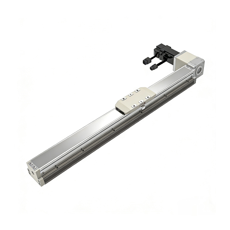 Belt Driven Dust-Proof Rail-Embedded Linear Module
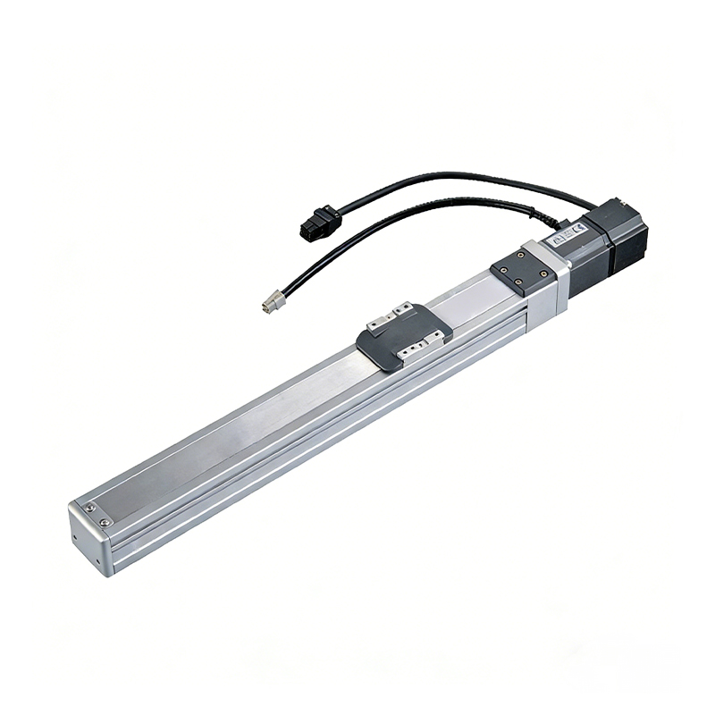 0.01mm High Precision Light Load Ball Screw Linear Module
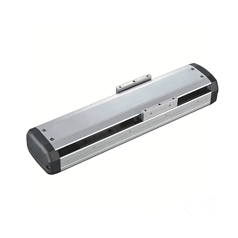 Ball Screw Linear Module with Built-in Sensor
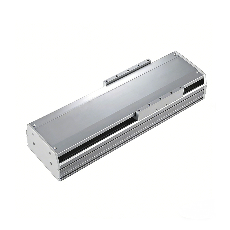 2000mm Long Stroke Ball Screw Linear Module
This 2000mm Long Stroke Ball Screw Linear Module is customized for large-range linear movement automation tasks, support...
READ MOREThis 2000mm Long Stroke Ball Screw Linear Module is customized for large-range linear movement automation tasks, support...
READ MOREThis 2000mm Long Stroke Ball Screw Linear Module is customized for large-range linear movement automation tasks, support...
READ MOREThis 2000mm Long Stroke Ball Screw Linear Module is customized for large-range linear movement automation tasks, support...
READ MORE
If you are interested in our products, please leave us a message. We look forward to providing you with
professional services!
Innovation and transcendence make factory intelligent manufacturing efficient and convenient!
+86 186 2508 0683
19962977901
sales@sz-tys.com
Building 5, Suzhou Mudu International Science and Technology Innovation Park, Jinfeng South Road, Suzhou City, Jiangsu Province, China
