


 English
 Français
 русский
 عربى
عربى Español
 Deutsch
Tel
+86 186 2508 0683

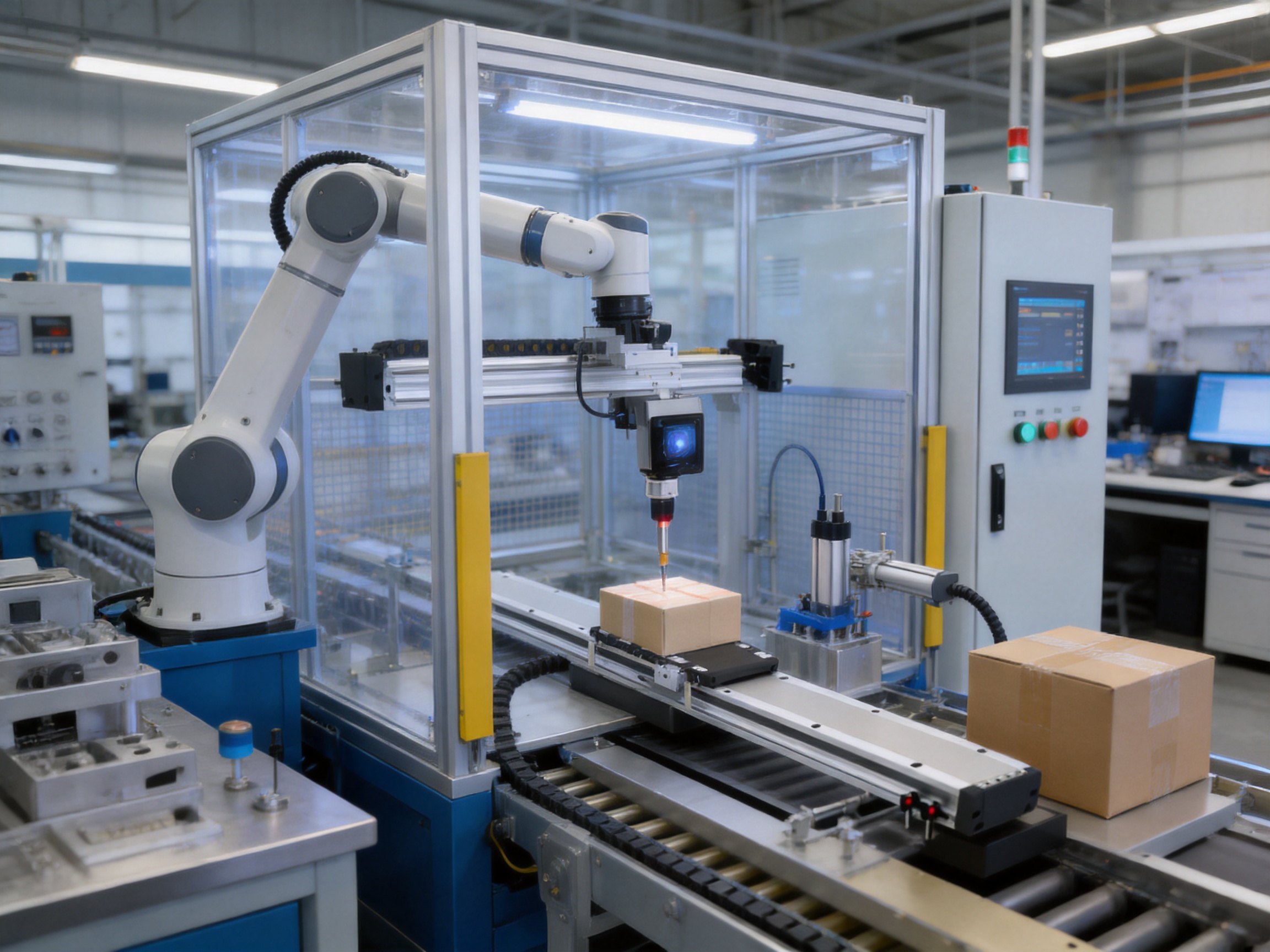
Modern manufacturing systems increasingly require motion components that combine high speed, high acceleration, compact dimensions, reliable load handling, and long-term protection against contamination. The TYSM8-L-F small linear motor module is designed for this demanding class of applications. With a body width of 82 mm, a maximum stroke of 1760 mm, a maximum speed of 2000 mm/s, and acceleration up to 2 G, it provides a high-performance solution for precise linear motion in compact automated equipment.
The module integrates a linear motor drive, dual internal linear guides, a heavy-duty carriage, and a fully dustproof enclosure. This combination allows it to operate in industrial environments where airborne particles, machining residue, dust, and other contaminants could reduce the service life or accuracy of a conventional open linear stage. Its enclosed design also helps simplify machine integration by reducing the need for additional protective covers and external sealing arrangements.
Manufactured by Suzhou Tongyousheng Electronic Technology Co., Ltd., the module reflects the company’s focus on electric cylinders, linear motion modules, linear motor systems, servo presses, robotic axes, and multi-degree-of-freedom motion platforms. The product is intended for positioning, transfer, inspection, loading, unloading, dispensing, assembly, and other applications that require responsive and repeatable linear movement.
The TYSM8-L-F is a small linear motor module built around a direct-drive electromagnetic motion principle. Instead of relying on a mechanical screw, belt, or rack-and-pinion transmission to convert rotary motor motion into linear travel, a linear motor generates thrust directly along the movement axis. This architecture reduces the number of mechanical transmission components between the motor and the carriage.
Direct linear drive can provide several practical benefits. It supports rapid acceleration and deceleration, enables high travel speeds, reduces mechanical backlash, and makes frequent short-distance movements easier to control. Because the drive does not require a conventional screw or belt transmission, the module is well suited to applications involving rapid indexing, repeated positioning, and dynamic motion profiles.
The TYSM8-L-F adds mechanical support and environmental protection to the direct-drive concept. Its built-in dual-guide arrangement supports the carriage on two linear guide paths, improving resistance to tilting and load-induced deflection. The heavy-duty carriage is designed to distribute external loads across the guide system, while the enclosed body protects internal elements from dust and industrial contamination.
With an 82 mm body width, the module occupies relatively little machine space compared with many larger industrial linear stages. At the same time, its maximum stroke of 1760 mm allows it to serve both compact workstations and longer transfer applications. This combination of narrow body geometry and long travel makes it particularly useful where equipment designers need to preserve floor space without sacrificing working range.
| Specification | Value |
|---|---|
| Product model | TYSM8-L-F |
| Product type | Small linear motor module |
| Body width | 82 mm |
| Maximum speed | 2000 mm/s |
| Continuous thrust | 98 N |
| Maximum stroke | 1760 mm |
| Maximum acceleration | 2 G |
| Maximum stated load | 20 kg at 0.5 m/s and 0.5 G |
| Guide configuration | Built-in dual linear guides |
| Environmental design | Fully dustproof enclosure |
| Nominal service life | 10,000 km under normal use within catalog specifications |
The stated performance values should be evaluated together with the actual load, installation direction, acceleration, travel profile, duty cycle, external moments, and working environment. The maximum load rating is not a universal value for every operating condition. The detailed loading tables provide more appropriate guidance for applications involving higher acceleration, different mounting directions, or greater dynamic demands.
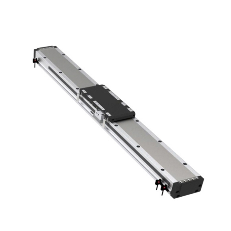
Built-in Dual-Guide Fully Dustproof Small Linear Motor Module
A major advantage of this module is its linear motor drive. In a conventional motorized linear axis, the motor often rotates a screw, belt, or rack. The transmission then creates the required linear motion. Each additional mechanical transmission element introduces considerations such as friction, wear, backlash, elastic deformation, lubrication, alignment, and maintenance.
A linear motor produces force directly along the axis. This can simplify the motion chain and reduce the mechanical compliance associated with a belt or long screw. The result is a responsive axis capable of rapid changes in velocity and direction. For applications involving high-frequency pick-and-place cycles or short indexing movements, direct drive can improve cycle time and reduce the delay associated with mechanical transmission components.
The maximum speed of 2000 mm/s gives the module considerable capability for rapid transfer. High speed is useful in semiconductor-related handling, inspection systems, packaging machinery, automated storage interfaces, and assembly equipment where the carriage must move quickly between work positions. The speed rating also provides design headroom for applications that operate below the maximum value but still require fast positioning.
The module is specified for up to 2 G maximum acceleration. High acceleration allows the carriage to reach its target speed over a shorter distance and reduces the time required for short moves. It can also improve throughput when the available travel distance is limited. However, acceleration must always be selected according to the payload, center of gravity, guide loading, mounting arrangement, and required positioning performance.
The continuous thrust rating is 98 N. This indicates the sustained thrust capability under the applicable thermal and operating conditions. Continuous thrust is different from a short-duration peak force rating. When selecting the module, engineers should calculate the force needed to accelerate the payload, overcome friction, manage vertical or inclined loads, and compensate for external process forces. The continuous thrust value should be compared with the calculated operating requirement rather than treated as a simple payload conversion.
Direct linear motion eliminates the need for a conventional screw or belt as the primary motion transmission element. This can reduce backlash and support more consistent bidirectional positioning. It also makes the axis less dependent on the condition of belts, nuts, pulleys, or gear teeth. With fewer transmission components, the design may offer reduced mechanical maintenance and more predictable dynamic behavior over the service life of the machine.
Linear motors are especially valuable in systems that require frequent acceleration and deceleration. Repetitive starts and stops can create wear in mechanical transmissions, particularly when a belt is repeatedly tensioned or when a screw and nut experience continuous reversals. The direct-drive structure avoids many of these wear mechanisms, although the guides, bearings, seals, cables, and mounting structure still require appropriate maintenance.
Another advantage is the possibility of flexible motion profiles. A suitable servo controller can manage speed, acceleration, deceleration, position, and force-related parameters according to the application. This allows one module to perform different movement patterns, including rapid transfer, gentle approach, synchronized motion, and precise positioning.
The module’s built-in dual-guide structure is central to its mechanical performance. A single guide may support linear travel, but it can be more sensitive to offset loads, rotational moments, and unevenly distributed payloads. Two integrated guides provide a wider support base and help resist pitch, yaw, and roll effects caused by the load and its center of gravity.
The heavy-duty carriage is designed to work with the dual-guide arrangement. It provides a stable mounting surface for tooling, grippers, workpieces, sensors, fixtures, or other equipment. By distributing the load across the guide system, the carriage can help preserve motion stability during acceleration and deceleration.
This structure is particularly important when the payload is not centered directly over the carriage. In real industrial equipment, the payload may extend outward, be mounted on a bracket, or carry a tool with an offset center of gravity. Such arrangements generate moments that can affect guide loading and positioning accuracy. The dual-guide design helps manage these loads more effectively than a narrow single-support configuration.
The catalog lists static loading moments of 1568 N·m for MY, 1568 N·m for MP, and 1196 N·m for MR. These values represent the specified moment capacity about the relevant axes under the stated catalog conditions. Engineers should compare the actual load moment with the appropriate value, taking into account the payload mass, the distance from the guide center, external forces, and dynamic acceleration.
| Static moment item | Catalog value | Engineering consideration |
|---|---|---|
| MY | 1568 N·m | Evaluate loads producing moment about the applicable lateral axis |
| MP | 1568 N·m | Consider offset payloads and acceleration-related overturning effects |
| MR | 1196 N·m | Check rotational loading generated by eccentric tooling or fixtures |
The torque values are based on the center of gravity reference described in the product information. They should not be interpreted as permission to exceed the recommended load tables. For high-speed operation, the dynamic moment may be greater than the static moment because acceleration, deceleration, vibration, and process forces act together.
The dual-guide configuration can also contribute to improved repeatability. A rigid carriage and stable guide base help prevent small changes in orientation as the carriage moves along the stroke. This is beneficial for applications such as vision inspection, dispensing, laser processing, and precision assembly, where the tool orientation must remain consistent throughout travel.
Contamination protection is one of the product’s most important differentiating features. Many linear stages use exposed rails, belts, screws, or moving components. These open structures may perform effectively in clean environments, but airborne dust and process residue can accumulate on guideways and transmission surfaces. Contamination may increase friction, create irregular motion, shorten component life, or raise maintenance requirements.
The TYSM8-L-F uses a fully dustproof enclosure to protect its internal motion components. The enclosed architecture is intended for industrial environments where dust is a practical concern. Examples include material handling, woodworking-related machinery, abrasive processing, powder-handling equipment, general fabrication, and production lines where debris may be generated by nearby processes.
A sealed or enclosed structure can also improve machine cleanliness. When moving parts are covered, the risk of lubricant or internal residue reaching nearby products may be reduced. This is valuable in automated production systems that require controlled handling and a neat equipment layout. The exact environmental suitability must still be confirmed for the specific dust type, particle size, temperature, humidity, cleaning method, and chemical exposure.
Dust protection does not eliminate the need for correct installation. Cable routing, mounting surfaces, end interfaces, fasteners, and external connections should be arranged according to the product’s technical documentation. The module should not be exposed to conditions beyond its specified environmental limits. If the machine requires washdown, corrosive chemical resistance, or operation in explosive atmospheres, the full system specification must be reviewed before selection.
Compared with an open linear motor stage, a fully enclosed model may reduce the need for additional machine guarding around the rail area. This can simplify the overall equipment design and reduce the number of external covers that must be fabricated. It may also make routine visual inspection easier because the main motion body is a compact, protected assembly.
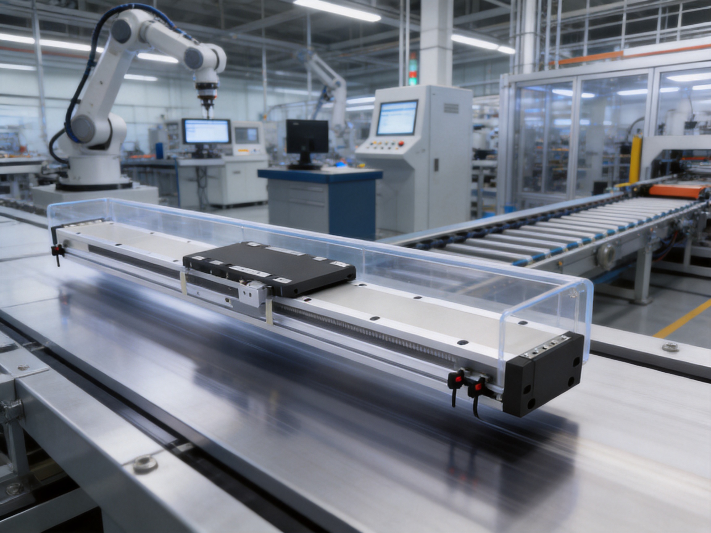
The module supports a maximum stated load of 20 kg under the specified condition of 0.5 m/s and 0.5 G. This rating provides a useful reference for moderate-speed horizontal operation. It should not be applied without adjustment to every speed and acceleration combination.
As speed and acceleration increase, the permissible payload generally decreases. Higher acceleration produces greater inertial force, while higher travel speed may increase vibration, stopping distance, and dynamic guide loading. The product information includes load and allowable travel-related values for horizontal and wall-mounted installations at several velocity and acceleration conditions.
For horizontal installation at 0.5 m/s and 5 m/s², the listed payload conditions include 10 kg, 15 kg, and 20 kg, with corresponding catalog values for A, B, and C. At 0.8 m/s and 8 m/s², the listed payload conditions include 10 kg, 15 kg, and 18 kg. At 1 m/s and 10 m/s², the listed payload conditions include 5 kg, 10 kg, and 15 kg. At 1.5 m/s and 15 m/s², the listed payload conditions include 5 kg, 6 kg, and 7 kg. At 2.0 m/s and 20 m/s², the listed payload conditions include 2 kg, 3 kg, and 4 kg.
These figures demonstrate an important selection principle: maximum speed and maximum payload are not normally available at the same time. A system designer should identify the required payload first, then determine the required motion time, speed, acceleration, and travel distance. Selecting a module only by its headline maximum speed can result in an unsuitable operating point.
Wall-mounted installation has its own load limits and should be evaluated separately. The orientation changes the direction of gravitational loading and may affect guide forces, carriage stability, and motor requirements. The catalog lists different payload values for wall-mounted use, including conditions at 0.5 m/s and 5 m/s², 0.8 m/s and 8 m/s², 1 m/s and 10 m/s², 1.5 m/s and 15 m/s², and 2.0 m/s and 20 m/s².
Ceiling-mounted inverted operation is not covered by the standard specifications. If the application requires inverted installation, the manufacturer should be consulted for confirmation of allowable loads, mounting requirements, lubrication, cable routing, and safety provisions.
First, determine the total moving mass. This includes the workpiece, tooling, brackets, cable carriers, sensors, fixtures, and any components attached to the carriage. The payload should not be limited to the product being transferred.
Second, calculate the required acceleration and deceleration. The motion profile should include the distance needed to accelerate, travel at constant speed, and decelerate. Short movements may never reach the nominal maximum speed, making acceleration and settling time more important than top speed.
Third, calculate the external moments. Measure the distance from the carriage reference center to the payload center of gravity. Include forces generated by gripping, pressing, dispensing, cutting, contact, cable drag, and process tooling.
Fourth, review the installation direction. Horizontal, wall-mounted, inclined, and inverted arrangements impose different loads on the guide and drive system. The module should be mounted on a sufficiently rigid and accurately aligned machine structure.
Finally, verify thermal duty, operating cycle, environmental conditions, encoder or feedback requirements, controller compatibility, and emergency stopping behavior. A complete motion analysis is more reliable than selecting the module by one specification alone.
The product is available with multiple stroke and overall length configurations. This supports machine builders that need to standardize on one module family while offering different working ranges to end users. The catalog dimensions show a modular relationship among the K value, N value, overall length L, stroke, and module weight.
The first configuration table covers K values from 6 to 20. The corresponding N values range from 2 to 9, while listed overall lengths range from 334 mm to 1174 mm. Module weights in this range extend from 5.6 kg to 12 kg. A second configuration table covers K values from 20 to 34, with N values from 9 to 16, overall lengths from 1234 mm to 2014 mm, and module weights from 12.5 kg to 19 kg.
| K value | N value | Overall length L | Module weight |
|---|---|---|---|
| 6 | 2 | 334 mm | 5.6 kg |
| 8 | 3 | 454 mm | 6.0 kg |
| 10 | 4 | 574 mm | 7.0 kg |
| 12 | 5 | 694 mm | 8.0 kg |
| 14 | 6 | 814 mm | 9.0 kg |
| 16 | 7 | 934 mm | 10.0 kg |
| 18 | 8 | 1054 mm | 11.0 kg |
| 20 | 9 | 1174 mm | 12.0 kg |
| K value | N value | Overall length L | Module weight |
|---|---|---|---|
| 20 | 9 | 1234 mm | 12.5 kg |
| 22 | 10 | 1354 mm | 13.5 kg |
| 24 | 11 | 1474 mm | 14.5 kg |
| 26 | 12 | 1594 mm | 15.5 kg |
| 28 | 13 | 1714 mm | 16.5 kg |
| 30 | 14 | 1834 mm | 17.5 kg |
| 32 | 15 | 1954 mm | 18.5 kg |
| 34 | 16 | 2014 mm | 19.0 kg |
The catalog source contains repeated stroke headings in the dimensional tables, so the exact relationship between each configuration code and usable stroke should be confirmed with the manufacturer during ordering. This is a normal engineering step for a configurable linear module. Designers should obtain the latest dimensional drawing, mounting-hole pattern, carriage dimensions, cable outlet location, stroke definition, and end-clearance requirements before finalizing the machine frame.
A longer module generally increases structural weight and may affect dynamic performance, support requirements, packaging, and transportation. The machine base should be designed to avoid bending or vibration across the full module length. For long travel applications, the installation surface must provide continuous or appropriately spaced support according to the manufacturer’s mounting recommendations.
The performance of a linear motor module depends not only on its design concept but also on manufacturing quality. Guide alignment, carriage flatness, enclosure geometry, motor assembly, electromagnetic spacing, dimensional tolerances, and final inspection all influence motion quality. A high-speed axis requires accurate control of these factors because small geometric errors can become more significant during rapid acceleration or precision positioning.
Suzhou Tongyousheng Electronic Technology Co., Ltd. operates as a high-tech enterprise integrating research and development, production, and sales. The company has an experienced research and development team, advanced design software, high-precision CNC machining centers, and a portfolio of core patents. These capabilities support the development and production of electric cylinders, linear motion modules, linear motor modules, servo presses, robotic seventh axes, and multi-degree-of-freedom platforms.
Advanced design software allows engineers to evaluate the module’s mechanical structure before production. Three-dimensional modeling can be used to check carriage geometry, enclosure interfaces, guide placement, cable routing, mounting holes, and possible interference with surrounding equipment. Motion and load calculations help determine whether the selected guide spacing, carriage size, and structural sections are appropriate for the intended application.
For a direct-drive module, design work must also consider the relationship between electromagnetic components and mechanical guide accuracy. The motor force-generating elements require suitable positioning along the travel path, while the carriage must move smoothly without excessive variation in air gap or alignment. The enclosure must protect the internal components without creating friction, contact, or thermal limitations.
High-precision CNC machining centers support the production of structural components with controlled dimensions and repeatable geometry. Machined carriage surfaces, mounting interfaces, guide seats, and end structures must maintain appropriate flatness and positional relationships. Accurate machining can reduce assembly correction work and help achieve consistent module performance across production batches.
CNC manufacturing also enables the production of customized interfaces. Machine builders may require special carriage holes, end fittings, sensor arrangements, cable outlets, or mounting brackets. A strong in-house or coordinated machining capability helps the supplier respond to these requirements more efficiently than a supplier relying only on fixed standard components.
Assembly quality is especially important for dual-guide linear modules. The two guides must work together without excessive preload, binding, or uneven resistance. The carriage, motor components, enclosure, and end sections must be assembled with attention to parallelism and alignment. A carefully controlled assembly process helps ensure that the carriage can travel smoothly across the full stroke.
Alignment also affects noise, heat generation, energy consumption, and service life. If a guide is misaligned, the system may experience localized loading that is not obvious during a basic operational check. Professional assembly and inspection procedures help reduce this risk.
Product verification may include dimensional inspection, travel smoothness checks, electrical tests, speed and acceleration testing, load evaluation, noise observation, and confirmation of control-system communication. The exact inspection plan depends on the product configuration and customer requirements.
For an industrial linear motor module, the verification process should consider the full movement range rather than only a short section near the center. Long-stroke units can exhibit different behavior at different positions if the support structure, cable routing, or guide alignment is not consistent. Checking the entire stroke helps identify issues before shipment.
The company’s integration of research, manufacturing, and sales supports technical communication during the selection process. This is valuable when the application involves unusual mounting, special payload geometry, multi-axis coordination, or integration with servo control equipment.
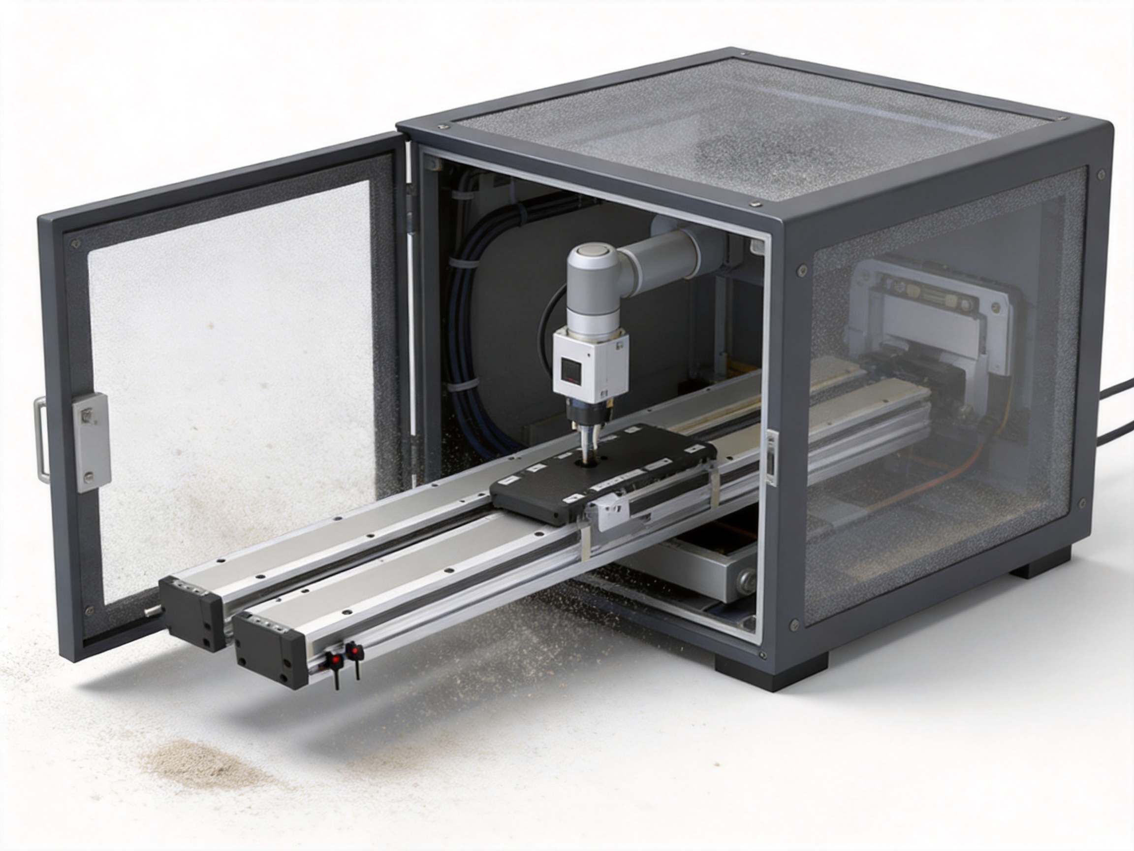
The TYSM8-L-F offers several advantages compared with conventional screw-driven, belt-driven, or open linear modules. The most important advantage is the combination of direct linear motor drive and enclosed dual-guide mechanics.
Screw-driven modules can provide strong thrust and accurate positioning, but their maximum speed may be limited by screw length, critical speed, inertia, nut wear, and heat generation. Long screws may require special support arrangements and can become more difficult to manage as stroke increases. A linear motor avoids screw whip and nut contact, making it more suitable for long, fast travel where rapid acceleration is required.
A screw-driven axis also contains a nut and screw interface that requires lubrication and may gradually wear. The TYSM8-L-F still requires proper guide and system maintenance, but its direct-drive principle removes the screw-nut transmission from the primary motion path. This can support lower mechanical backlash and faster response.
Belt-driven modules are often economical and lightweight, but the belt can stretch, wear, or require tension adjustment. Elasticity may influence positioning response, especially during acceleration and reversal. Belt systems may also be more vulnerable to contamination when the belt and pulleys are exposed.
The TYSM8-L-F uses a fully dustproof body and direct linear drive rather than an exposed timing belt. This helps reduce concerns related to belt contamination, belt tension, and belt replacement. Its rigid dual-guide carriage also offers a more stable platform for offset loads and precision tooling.
Open linear motor stages can achieve excellent speed and precision, but their exposed guideways and motor elements may require a clean operating environment or additional protective covers. The TYSM8-L-F is designed to provide the benefits of linear motor motion within a dustproof enclosure.
The enclosed format can reduce the effort required to protect the axis from surrounding contamination. It is therefore attractive for industrial machinery that cannot guarantee a cleanroom-like environment. The final suitability depends on the actual environmental conditions, but the protection concept gives machine designers an important advantage.
A narrow single-guide module may save space, but it can be less suitable for payloads with a large offset or substantial overturning moment. The TYSM8-L-F uses dual built-in guides and a heavy-duty carriage to provide a broader support arrangement. This can improve stability when the carriage supports a gripper, fixture, sensor head, or process tool positioned away from the module centerline.
The module’s combination of speed, stroke, compact width, load capability, and contamination protection makes it suitable for a broad range of industrial applications.
In transfer systems, the carriage may carry a gripper or vacuum tool between loading and unloading positions. Fast acceleration can reduce the time between cycles, while the dual-guide carriage helps maintain tool stability. The dustproof enclosure is useful where the transfer station is located near machining, cutting, packaging, or bulk material operations.
Vision inspection systems often require a camera or sensor to move accurately across a workpiece or series of workstations. Smooth travel and repeatable carriage behavior support consistent image acquisition. The module can be used for scanning, camera indexing, part presentation, or movement between inspection zones.
Automated assembly equipment may require components to be positioned rapidly before a controlled insertion, fastening, pressing, or joining operation. The linear motor module can provide rapid approach motion followed by a lower-speed positioning phase. Its compatibility with standard control systems facilitates integration into multi-axis equipment.
Dispensing systems require controlled movement of a nozzle relative to a workpiece. The module can support adhesive dispensing, sealant application, coating, marking, or other linear process operations. Engineers should evaluate the required path accuracy, velocity consistency, vibration, and process forces.
Packaging systems often use fast horizontal transfer to move products, cartons, trays, or containers. The module’s long-stroke capability can support movement between separated stations, while the compact width helps preserve machine layout space. Its enclosed body is appropriate for production environments where paper fibers, dust, or packaging debris may be present.
The module can serve as a robotic seventh axis or auxiliary motion axis. A robot mounted on the carriage can access multiple work positions along a longer path, extending the operating range without requiring a larger articulated robot. The load and moment analysis is especially important in this configuration because the robot and its payload create significant dynamic forces.
Equipment manufacturers often need to package several axes, sensors, controllers, and process tools into a limited footprint. The 82 mm body width provides a practical option where a full-size linear stage would consume too much space. A modular stroke range also allows the same product family to be used across multiple machine models.
The product is compatible with standard control systems for convenient integration. In a typical application, the linear motor module is connected to a suitable servo drive, feedback system, motion controller, and safety circuit. The exact electrical interface, feedback type, cable arrangement, and drive parameters should be confirmed for the selected configuration.
Control-system commissioning should include motor identification, travel-limit verification, direction confirmation, homing or absolute-position setup, acceleration and deceleration tuning, and emergency-stop validation. The machine builder should also confirm that the controller can manage the required speed, continuous thrust, position resolution, and motion profile.
Because linear motors can respond quickly, tuning should be performed carefully. Excessive gain may cause vibration or overshoot, while insufficient gain may reduce responsiveness or settling performance. Mechanical rigidity, carriage load, cable drag, and tool flexibility all influence servo behavior.
For high-speed motion, safety functions should be evaluated as part of the complete machine. Emergency stopping distance, deceleration limits, protective guarding, access control, and residual movement must be considered. A linear motor does not automatically hold the carriage in place when power is removed, so vertical or inclined applications may require additional mechanical safety provisions.
The stated guaranteed service life is 10,000 km when the product is used normally and in compliance with the specifications in the catalog. Service life is affected by payload, speed, acceleration, duty cycle, mounting accuracy, environmental contamination, external moments, lubrication conditions, and maintenance practice.
A dustproof enclosure helps protect internal components, but it should not be treated as a substitute for inspection. Machine operators should periodically check mounting bolts, cable connections, external seals, unusual noise, temperature, vibration, and motion smoothness. Any change in positioning behavior or motor current may indicate a developing issue.
The guide system should be maintained according to the manufacturer’s recommendations. Lubrication intervals depend on operating conditions and environmental exposure. Contaminated or incorrect lubricant may reduce performance, so only approved materials and procedures should be used.
Long-term reliability also depends on the machine frame. A flexible or distorted base can introduce alignment errors even when the module itself is manufactured accurately. The mounting surface should be clean, flat, rigid, and capable of supporting the module along its length. Fasteners should be tightened in the recommended sequence and torque range.
In dusty environments, the surrounding machine design should prevent dust from being directed toward interfaces, cable outlets, and end sections. External airflow, extraction systems, and process guards should be arranged so that contamination protection is not unnecessarily challenged.
Before installation, confirm the module length, usable stroke, carriage orientation, mounting holes, cable exit direction, accessory requirements, and controller compatibility. The module should be handled carefully to avoid impact or twisting, particularly on long configurations.
The mounting frame should be machined or prepared to the required flatness and straightness. If the base is uneven, tightening the module onto it may distort the body and increase guide resistance. Long modules may require multiple support points or a continuous support surface according to the installation drawing.
Attached tooling should be positioned as close as practical to the carriage support plane. Reducing the distance to the center of gravity lowers the generated moment and can improve dynamic behavior. If an extended bracket is unavoidable, the bracket should be designed with sufficient stiffness to prevent vibration or deflection.
After installation, move the carriage slowly through the full travel range before applying high acceleration. Confirm that there is no interference, cable tension, unusual resistance, or unexpected noise. Verify the home position and limits before commissioning automatic cycles.
For wall-mounted use, account for the direction of gravity and the effect of the payload on guide loading. For ceiling-mounted inverted operation, obtain specific confirmation from the manufacturer because standard specifications do not apply to this arrangement.
Suzhou Tongyousheng Electronic Technology Co., Ltd. was established in 2013 and has continued to expand its product development and manufacturing capabilities. Its product range includes electric cylinders, linear modules, linear motor modules, servo presses, robotic seventh axes, six-degree-of-freedom motion platforms, algorithmic control software, and multi-degree-of-freedom platform linkage systems.
This broad product portfolio gives the company experience across both individual motion components and complete motion subsystems. Knowledge gained from electric cylinders and servo presses can support force-control applications, while experience with motion platforms and robotic axes can support coordinated multi-axis integration.
The company works with state-owned enterprises, defense technology institutions, and universities to promote cooperation among industry, academia, and research. Such cooperation can contribute to the development of control algorithms, structural improvements, motion simulation capabilities, and application-specific automation solutions.
The company’s stated values include quality, reputation, innovation, and development. Its mission is to advance industrial progress through innovation and craftsmanship while building long-term customer trust. For international machine builders, this combination of engineering, manufacturing, and application support is important when a standard product must be adapted to a specific production line.
When requesting a quotation or technical review, customers should provide the required stroke, total moving mass, desired speed, acceleration, installation direction, payload center of gravity, external moments, operating cycle, environmental conditions, and control-system details.
It is also helpful to provide a drawing of the payload and tooling. A simple dimensional sketch showing the mounting surface, center of gravity, offset distances, and external forces allows the supplier to assess guide loading more accurately. If the carriage will carry a robot, camera, gripper, or process head, the complete assembly should be included in the calculation.
Environmental information should include dust type, particle size if known, temperature, humidity, cleaning method, corrosive substances, and nearby vibration sources. “Dusty environment” can describe many different conditions, and the actual suitability of the enclosure depends on the specific exposure.
Control information should include the preferred servo drive, communication protocol, feedback requirement, power supply, cable length, and safety architecture. Confirming these points early can prevent delays during commissioning.
For long-stroke configurations, ask for the latest dimensional and mounting drawings. The product data indicates multiple configurations with different lengths and weights, so the selected model must be matched to the required usable stroke and machine envelope.
The TYSM8-L-F is a compact, high-speed linear motor module for precise linear positioning, transfer, inspection, assembly, and automated handling. It is designed for applications requiring direct-drive motion, dual-guide carriage support, and dust protection.
The maximum listed speed is 2000 mm/s. The actual allowable speed depends on payload, acceleration, travel profile, installation direction, controller settings, and environmental conditions.
The maximum listed stroke is 1760 mm. Multiple module length configurations are available, and the exact usable stroke should be confirmed from the dimensional drawing for the selected configuration.
The maximum stated load is 20 kg under the condition of 0.5 m/s and 0.5 G. Higher speed or acceleration generally requires a lower payload. The detailed catalog load tables should be used for final selection.
Dual built-in guides provide a wider support arrangement for the carriage. They help resist tilting and rotational moments caused by offset payloads, tooling, and acceleration. This can improve stability and repeatability compared with a narrow single-guide structure.
The fully dustproof enclosure is designed to protect internal components from contamination and makes the module suitable for many dusty industrial environments. The exact suitability depends on the type and concentration of dust, temperature, humidity, cleaning conditions, and other environmental factors.
Wall-mounted installation is included in the product information, but the allowable load changes with installation direction. Vertical, inclined, or wall-mounted applications should be checked using the appropriate load data. Ceiling-mounted inverted use is not covered by the standard specifications and requires consultation.
No. The module uses a linear motor for direct linear thrust, so it does not rely on a screw, belt, or rack as the primary motion transmission mechanism.
The guaranteed service life is stated as 10,000 km when the module is used normally and within the catalog specifications. Actual life depends on loading, acceleration, environmental conditions, mounting quality, maintenance, and duty cycle.
The module is described as compatible with standard control systems. The exact servo drive, feedback, communication interface, cable arrangement, and commissioning requirements should be confirmed for the selected model and application.
Check the required stroke, total moving mass, speed, acceleration, installation direction, center of gravity, external moments, environmental conditions, controller compatibility, mounting dimensions, and cable requirements. A technical drawing of the payload is recommended.
It can be considered for robotic auxiliary axes and seventh-axis applications, provided that the robot mass, payload, center of gravity, moments, acceleration, and safety requirements remain within the module’s allowable limits.
The TYSM8-L-F small linear motor module combines direct-drive performance with a compact 82 mm body, a maximum speed of 2000 mm/s, up to 2 G acceleration, 98 N continuous thrust, and a maximum stroke of 1760 mm. Its built-in dual guides and heavy-duty carriage provide a stable platform for payloads and offset tooling, while the fully dustproof enclosure helps protect the motion system in demanding industrial environments.
Compared with conventional screw-driven and belt-driven modules, the product offers the advantages of direct linear thrust, reduced reliance on mechanical transmission components, rapid response, and suitability for high-frequency motion. Compared with open linear motor stages, its enclosed construction provides an additional level of contamination protection. Compared with narrow single-guide designs, its dual-guide configuration offers improved support for external moments.
The product is supported by a company with experience in research, precision CNC manufacturing, automation components, servo pressing, robotic axes, and multi-degree-of-freedom motion systems. This combination of product engineering and manufacturing capability makes the module a practical option for machine builders seeking a compact, high-speed, and protected linear motion solution.
Final selection should always be based on a complete engineering review. Payload, acceleration, installation direction, external moments, environmental conditions, controller compatibility, and mounting accuracy all influence performance. When these factors are correctly evaluated, the TYSM8-L-F can provide a reliable foundation for high-speed positioning, material transfer, inspection, assembly, packaging, and other intelligent manufacturing applications.
1. TYSM8-L-F Product Information and Technical Parameter Tables, manufacturer-provided product materials.
2. Linear Motor Module Application and Selection Data, including horizontal and wall-mounted load conditions.
3. Static Loading Moment Data for MY, MP, and MR Axes, manufacturer product documentation.
4. Module Stroke, Length, Configuration, and Weight Tables, manufacturer dimensional information.
5. General Principles of Linear Motion System Design, industrial automation engineering reference material.
6. Servo Motion Control, Acceleration Profiles, Load Moment Evaluation, and Machine Safety Practices, technical engineering references.
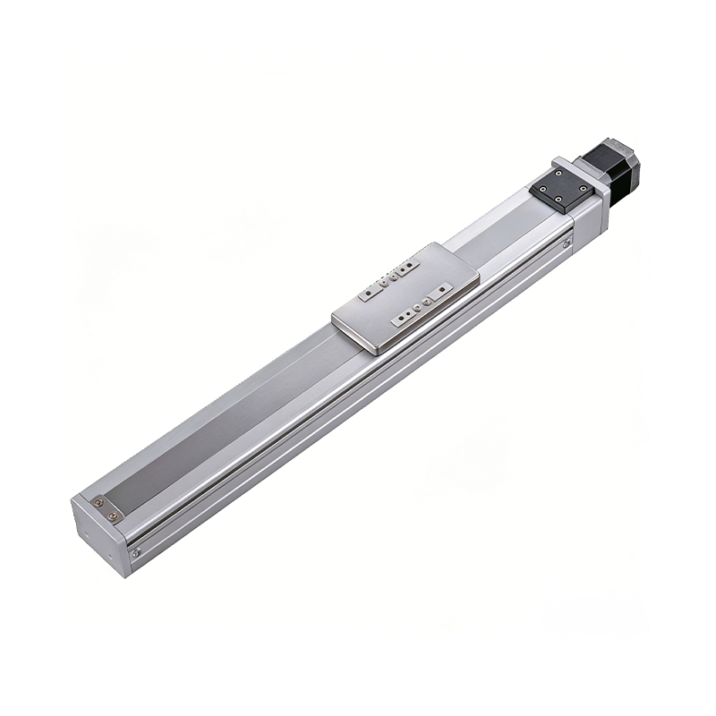 0.01mm High Precision Ball Screw Driven Rail-Embedded Linear Module
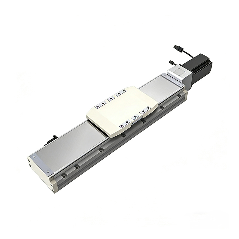 Heavy Load Ball Screw Driven Rail-Embedded Linear Module
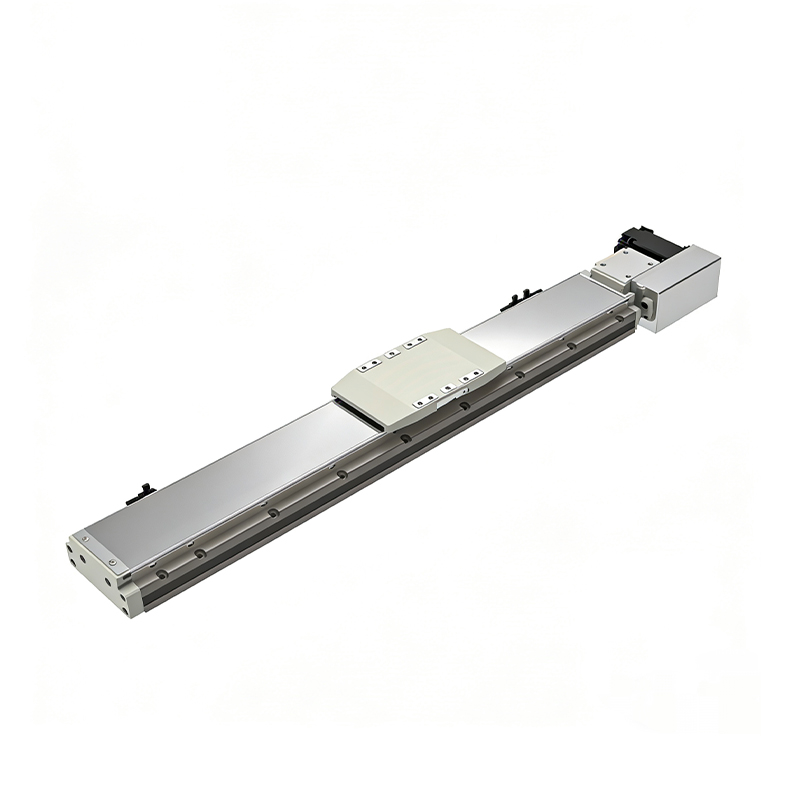 110KG Load Long Stroke Rail-Embedded Linear Module
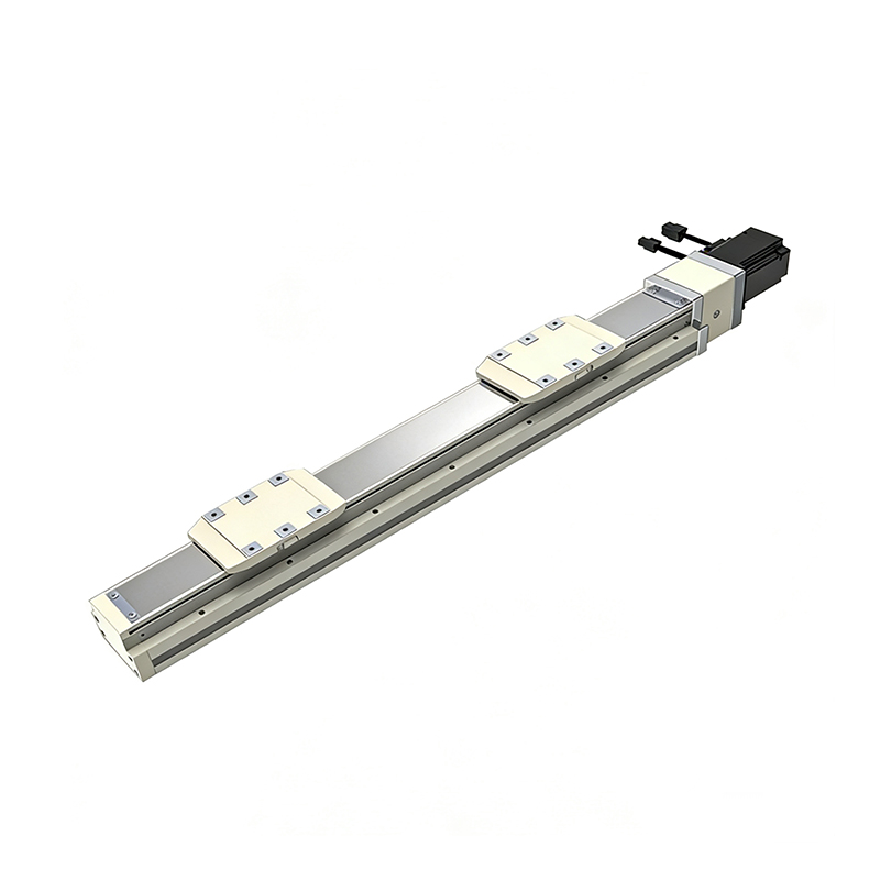 Dual-Slider High Precision Rail-Embedded Linear Module
 Belt Driven Dust-Proof Rail-Embedded Linear Module
 0.01mm High Precision Light Load Ball Screw Linear Module
 Ball Screw Linear Module with Built-in Sensor
 2000mm Long Stroke Ball Screw Linear Module
This 2000mm Long Stroke Ball Screw Linear Module is customized for large-range linear movement automation tasks, support...
READ MOREThis 2000mm Long Stroke Ball Screw Linear Module is customized for large-range linear movement automation tasks, support...
READ MOREThis 2000mm Long Stroke Ball Screw Linear Module is customized for large-range linear movement automation tasks, support...
READ MOREThis 2000mm Long Stroke Ball Screw Linear Module is customized for large-range linear movement automation tasks, support...
READ MORE
If you are interested in our products, please leave us a message. We look forward to providing you with
professional services!
Innovation and transcendence make factory intelligent manufacturing efficient and convenient!
+86 186 2508 0683
19962977901
sales@sz-tys.com
Building 5, Suzhou Mudu International Science and Technology Innovation Park, Jinfeng South Road, Suzhou City, Jiangsu Province, China
