


 English
 Français
 русский
 عربى
عربى Español
 Deutsch
Tel
+86 186 2508 0683

Precision automation increasingly depends on motion components that can deliver repeatable positioning, stable transmission, compact installation, and dependable service over long operating cycles. The 0.01 mm High-Precision Light-Load Ball Screw Linear Module is designed for applications where every millimeter of machine space matters and where smooth, controlled movement is more important than carrying a heavy payload. It combines a compact linear structure, a C7 ball screw, a high-rigidity linear guide, and a 100 W AC servo motor configuration to provide a practical motion solution for precision equipment.
This ball screw linear module is intended for light-load horizontal, wall-mounted, and vertical applications. Its design supports strokes from 50 mm to 800 mm in 50 mm increments, with maximum speeds ranging from 250 mm/s to 1,000 mm/s depending on the selected screw lead. The module provides repeatability of ±0.01 mm, making it suitable for electronic component assembly, micro-instrument processing, semiconductor equipment, inspection systems, laboratory automation, and other applications requiring reliable short- and medium-stroke positioning.
Unlike a basic slide mechanism or an oversized industrial actuator, this module is optimized around the needs of compact precision systems. Its lightweight body helps reduce the mass placed on an upstream axis, while the ball screw and linear guide provide controlled, low-friction movement. The result is a balanced actuator platform for manufacturers that need precision without unnecessary bulk, excessive energy consumption, or overcapacity.
A ball screw linear module integrates the primary elements required for linear motion into one coordinated assembly. These elements generally include a structural body, a moving slider, a ball screw transmission, a linear guide, a motor connection, mounting interfaces, and a sensor arrangement. By combining these components into a prepared module, equipment designers can shorten mechanical integration time and reduce the number of individual parts that must be selected, aligned, and tested.
The featured module uses a compact structure intended for light-load operation. This design is especially valuable in precision machines in which the available installation area is limited. A smaller actuator can simplify machine layout, create more room for tooling and sensors, and reduce interference between adjacent axes. It can also help reduce the total moving mass of a multi-axis system.
The transmission system is based on a ball screw with a nominal diameter of 12 mm and C7 accuracy classification. Ball screw technology converts rotary motor motion into controlled linear movement through recirculating balls. Compared with a conventional sliding screw, a ball screw normally provides lower friction, improved efficiency, more consistent motion, and reduced wear when correctly lubricated and operated within its rated conditions.
The high-rigidity linear guide is specified as W24 × H8.5. The guide supports the slider and helps control movement along the axis. It also contributes to the module’s ability to resist small external disturbances and maintain stable travel under the recommended loading and moment conditions.
A 100 W AC servo motor is provided as the standard motor power specification. Depending on the system builder’s preferred control platform, compatible motor options include Mitsubishi, Panasonic, and Delta servo configurations. Horizontal versions are available without a brake, while vertical configurations can be equipped with a brake to help hold the load when power is removed.
The defining performance characteristic of this product is repeatability of ±0.01 mm. Repeatability describes how closely the module can return to the same position under consistent operating conditions. In production equipment, this characteristic is important for pick-and-place operations, dispensing, inspection, assembly, probing, alignment, and other repetitive tasks.
The module supports three ball screw lead choices: 5 mm, 10 mm, and 20 mm. Lead selection allows the user to balance speed, thrust, and load capacity. A 5 mm lead provides the highest rated thrust and the greatest payload capacity, while a 20 mm lead provides the highest maximum speed. The 10 mm lead offers an intermediate configuration for applications that need a balance between movement speed and force.
| Parameter | 5 mm Lead | 10 mm Lead | 20 mm Lead |
| Repeatability | ±0.01 mm | ±0.01 mm | ±0.01 mm |
| Maximum Speed | 250 mm/s | 500 mm/s | 1,000 mm/s |
| Maximum Horizontal Payload | 10 kg | 5 kg | 3 kg |
| Maximum Vertical Payload | 3 kg | 1.5 kg | 1.5 kg |
| Rated Thrust | 341 N | 170 N | 85 N |
The rated figures show why lead selection should be made according to the complete application rather than speed alone. A high-lead screw can move more quickly over the same motor rotation, but its mechanical advantage is lower. As a result, the rated thrust and allowable payload are reduced. Conversely, the 5 mm lead offers more thrust and a higher horizontal payload, making it suitable for applications in which the load is heavier or acceleration must be controlled with greater force.
For a light inspection head, camera assembly, sensor carrier, or electronic component tool, the 20 mm lead may provide the desired rapid movement. For a compact pressing, feeding, or positioning operation, the 5 mm lead may be more appropriate. The 10 mm lead is often a practical compromise for general automation.
Many competing motion solutions are designed around general industrial loads and may be physically larger than necessary for precision light-load equipment. An oversized actuator can increase the dimensions of the machine, raise the moving mass, and make cable routing or enclosure design more difficult. The compact construction of this module addresses those issues directly.
The available strokes range from 50 mm to 800 mm, with a 50 mm pitch between standard stroke options. This range covers short-stroke positioning tasks as well as longer linear transfers. A 50 mm stroke is useful for compact assembly heads, probing mechanisms, miniature feeding systems, and adjustment stages. Longer versions can be used for transfer axes, inspection travel, and component handling.
The module body length is configured according to the selected stroke and motor arrangement. For the motor-right, motor-left, and motor-bottom configurations, the overall length is generally 158 mm greater than the stroke. For the motor-exposed configuration, the overall length is generally 166 mm greater than the stroke. This information assists designers in preparing preliminary layouts and checking installation clearances before detailed mechanical integration.
The module is also available with several motor orientation arrangements. Motor-right-side and motor-left-side configurations can help adapt the actuator to the machine’s cable and drive layout. A motor-exposed version can be useful when the motor must remain accessible or when the structure around the actuator requires a different connection arrangement. A motor-bottom-side configuration can assist with low-profile machine designs or special mounting geometries.
Because the body is lightweight, the module is well suited to systems in which one axis is mounted on another. Reducing the mass of the upper axis can help lower the required capacity of the supporting axis and may improve acceleration performance. This advantage is particularly relevant to Cartesian robots, compact gantries, camera positioning systems, and multi-axis inspection equipment.
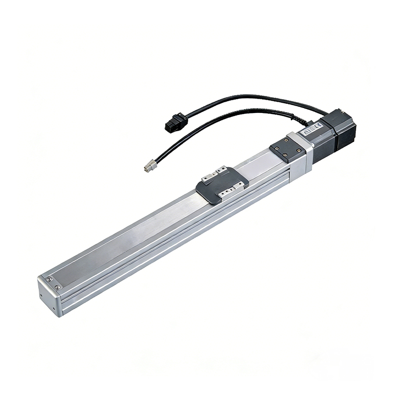
0.01mm High Precision Light Load Ball Screw Linear Module
The ball screw is central to the module’s positioning behavior. In a ball screw mechanism, the screw and nut are separated by rolling balls. This rolling contact reduces sliding friction and allows the motor’s torque to be converted into linear thrust with comparatively high efficiency. The design is suitable for repeated positioning movements and continuous low-load operation when installation, lubrication, and operating conditions are properly managed.
The specified C7 ball screw with a 12 mm diameter provides a practical solution for the module’s light-load operating range. It is not necessary to use a large, heavy screw for every application. Selecting a transmission sized for the expected load can help maintain a compact envelope while delivering sufficient force and service life.
The high-rigidity linear guide supports the moving platform and controls lateral motion. The guide must carry not only the direct payload but also the effects of acceleration, eccentric loading, and external moments. The W24 × H8.5 guide specification indicates a compact guide arrangement intended to preserve stiffness within the module’s small form factor.
Stable interaction between the ball screw and the linear guide is essential. If the guide is improperly mounted, misalignment can increase friction and reduce repeatability. For this reason, machine builders should install the module on a sufficiently flat and rigid reference surface. Mounting bolts should be tightened according to the equipment manufacturer’s recommended procedure, and the slider should not be forced laterally during installation.
The module’s structural design is intended to maintain stable transmission during long-term low-load continuous work. This feature is important in electronic and semiconductor equipment, where an axis may perform thousands or millions of small movements while carrying only a tool, sensor, camera, or miniature workpiece.
The product offers several practical advantages over generic linear actuators and improvised linear assemblies. The first is integrated engineering. A machine builder does not need to separately select a screw, guide, coupling, body, mounting hardware, and sensor arrangement and then verify their compatibility. The module brings these elements together in a coordinated design.
The second advantage is the combination of precision and compactness. Some low-cost linear slides prioritize economy but do not provide the same positioning stability, guide rigidity, or motor compatibility. Other high-capacity industrial actuators may provide more load capability than a light-load application requires. This module occupies a useful middle ground: it is designed for precise, repeatable motion while avoiding the unnecessary size associated with heavy-duty systems.
The third advantage is configuration flexibility. The three lead choices enable users to select between thrust and speed. The range of stroke options allows the same basic platform to be applied across multiple machine sizes. Several motor orientations support different mechanical layouts, and compatible servo motor brands provide more freedom when standardizing the electrical control system.
The fourth advantage is clear load and moment information. The module is specified with maximum payload values for horizontal and vertical installation, as well as static loading moment values. These data allow engineers to evaluate the actuator using actual center-of-gravity positions rather than relying only on a simple payload number.
| Static Loading Moment | Rated Value |
| MY | 16 N·m |
| MP | 20 N·m |
| MR | 19 N·m |
The torque values represent the center-of-gravity conditions indicated in the product information. In practical machine design, the payload should be evaluated together with its distance from the slider. A tool weighing less than the maximum rated payload may still exceed the allowable moment if its center of gravity is positioned too far from the guide.
The fifth advantage is suitability for standard servo control architectures. The listed Mitsubishi, Panasonic, and Delta motor and driver combinations make it easier for integrators to connect the module to an existing automation platform. This can reduce the need for unfamiliar drive hardware and simplify maintenance for factories that already use one of these control ecosystems.
The 5 mm lead configuration delivers a maximum speed of 250 mm/s, a horizontal payload rating of up to 10 kg, a vertical payload rating of up to 3 kg, and rated thrust of 341 N. It is the most force-oriented option in the product range.
This configuration may be selected for horizontal transfer, compact pressing support, feeding, positioning fixtures, and tooling applications that require a greater thrust reserve. It can also be useful where controlled movement is more important than maximum travel speed.
When the axis is installed vertically, the payload must be reduced to the specified vertical rating. Gravity continuously acts on the load in a vertical arrangement, and a brake-equipped servo motor is recommended where the load must be held safely when the motor is not energized.
The 10 mm lead configuration provides a maximum speed of 500 mm/s, a horizontal payload rating of up to 5 kg, a vertical payload rating of up to 1.5 kg, and rated thrust of 170 N. It is a balanced choice for general-purpose precision automation.
Typical uses may include inspection-head movement, component transfer, laboratory automation, feeder mechanisms, and compact Cartesian axes. It provides more speed than the 5 mm option while retaining a useful level of thrust for light and medium-light loads.
The 20 mm lead configuration provides the highest maximum speed, reaching 1,000 mm/s. Its horizontal payload rating is up to 3 kg, its vertical payload rating is up to 1.5 kg, and its rated thrust is 85 N.
This configuration is intended for fast travel and low-load motion. It may be suitable for camera positioning, rapid inspection, lightweight pick-and-place tooling, and applications in which the payload is small and cycle time is a major consideration.
High-speed operation requires careful attention to acceleration, deceleration, vibration, cable management, and end-of-stroke control. The rated maximum speed should not automatically be treated as the best operating speed for every application. A lower speed may be desirable when the payload has a high center of gravity or when the machine requires exceptionally smooth motion.
The stated repeatability of ±0.01 mm is a key reason to consider this module for precision equipment. Repeatability is influenced by the mechanical transmission, guide condition, servo tuning, load distribution, mounting rigidity, temperature, lubrication, and control parameters. Achieving the best practical result requires the module to be integrated into a stable mechanical and electrical system.
Machine designers should distinguish repeatability from absolute accuracy. Repeatability concerns the consistency of returning to a position, while absolute accuracy concerns the difference between the commanded position and the actual position across the full travel. If the application requires calibrated absolute accuracy, additional measurement, compensation, or external feedback may be necessary.
The module’s ball screw and linear guide are intended to provide stable movement during repeated low-load cycles. In electronic component assembly, for example, a tool may need to approach a workpiece at a controlled speed, stop at a defined position, complete an operation, and return repeatedly. Excessive mechanical play or inconsistent friction could lead to placement errors, connector damage, or inspection variation. A properly maintained ball screw module helps reduce these risks.
Servo tuning should be carried out after the module is installed with its actual tooling and payload. The inertia of the tool, the stiffness of the mounting structure, and the expected motion profile all affect servo response. Gradual acceleration and deceleration can reduce mechanical shock and help protect the screw, guide, coupling, and mounted equipment.
The product information specifies an external home sensor arrangement. Listed sensor options include EE-SX672 with NPN output and FC-SPX303Z-2M with NPN output. A home sensor provides a repeatable reference position for machine initialization, recovery, and coordinate registration.
In a typical automation sequence, the controller commands the module to move toward the home sensor at a controlled speed. Once the sensor is detected, the axis may reverse or continue at a lower speed to establish a more precise reference. The exact homing method depends on the servo drive, controller, sensor position, and application requirements.
Before commissioning, the electrical interface should be checked carefully. NPN sensors require compatible input circuitry and correct wiring of power, signal, and common connections. Sensor cables should be routed separately from high-power motor cables where possible to reduce electrical interference. The sensor position should also be protected from accidental impact by tooling or workpieces.
For applications requiring additional end-of-travel protection, machine builders may incorporate limit sensors or software travel limits. Software limits should not be treated as the only protection against overtravel. The machine’s safety design should account for unexpected commands, sensor failure, communication loss, and power interruption.
The module can be used in horizontal, wall-mounted, and vertical installation arrangements, provided the payload and overhang conditions remain within the stated limits. Installation orientation affects the allowable load because gravity, moments, and guide loading change with the position of the axis.
Horizontal mounting generally provides the highest payload capacity. Wall-mounted installation can be used when the actuator is fixed to a vertical machine frame, but the center of gravity and moment arm must be evaluated carefully. Vertical installation requires special consideration because the load is continuously influenced by gravity and because a sudden loss of power may allow the slider to move downward.
The allowable overhang data provide guidance for placing a payload relative to the slider. For the 5 mm lead, the horizontal values include payload examples of 5 kg and 10 kg, while the vertical values include 1 kg and 3 kg examples. For the 10 mm lead, the data include 3 kg and 5 kg horizontal cases and 1 kg and 1.5 kg vertical cases. For the 20 mm lead, the data include 2 kg and 3 kg horizontal cases and 1 kg and 1.5 kg vertical cases.
| Installation Type | Relevant Design Consideration |
| Horizontal | Use the selected lead’s horizontal payload rating and verify overhang in directions A, B, and C. |
| Wall-mounted | Check the payload and moment created by the vertical mounting surface and the tool center of gravity. |
| Vertical | Use the lower vertical payload rating, consider gravity, and select a brake-equipped motor when required. |
| Ceiling-mounted inverted use | Standard specifications do not apply; consult the supplier for confirmation and special requirements. |
The standard specifications do not apply to ceiling-mounted inverted use. This is an important limitation. Inverted installation can affect lubrication distribution, slider retention, cable routing, and load behavior. If a machine requires this arrangement, the design should be reviewed with the supplier before the module is ordered.
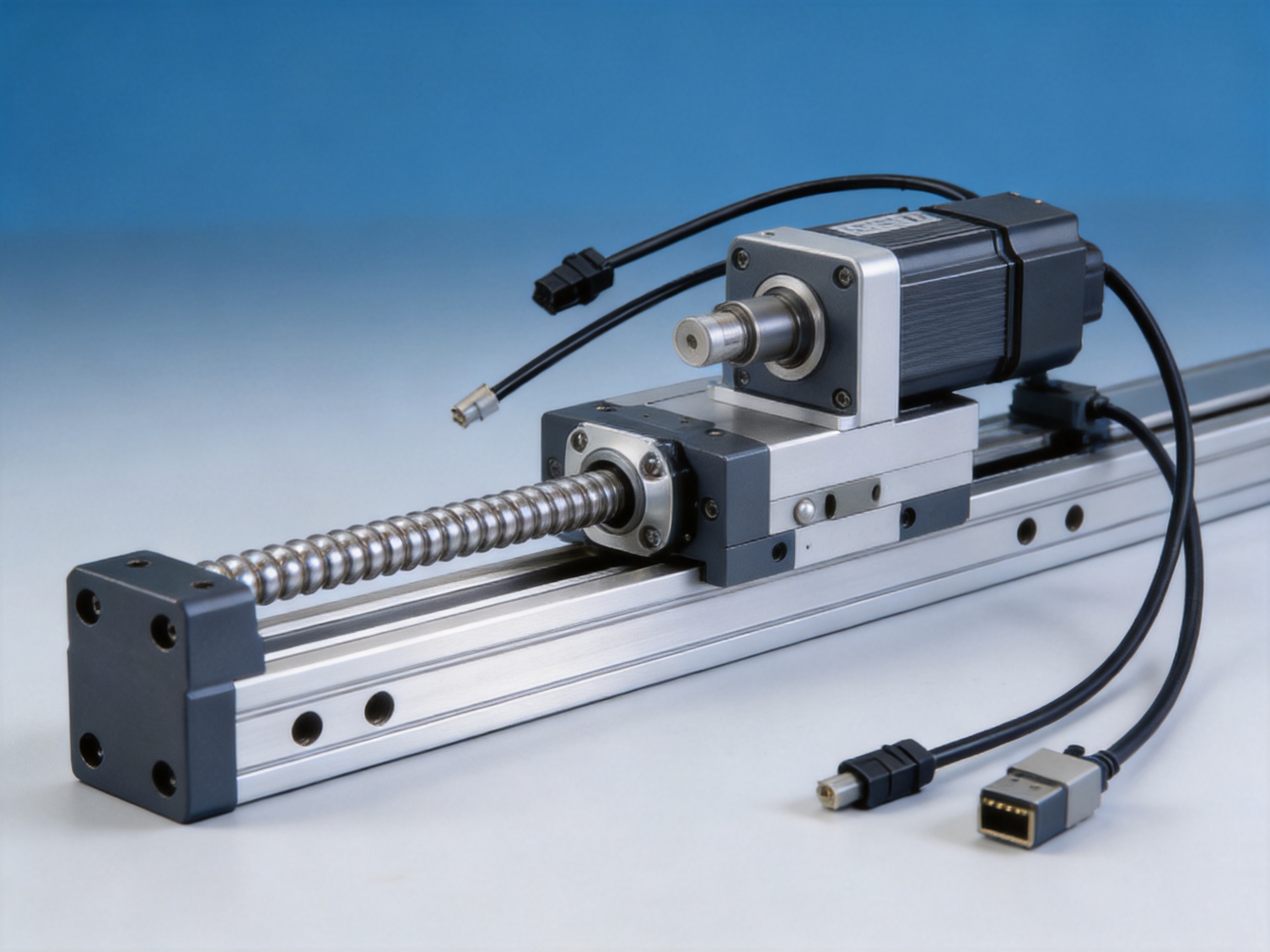
Standard stroke options are available from 50 mm to 800 mm in 50 mm increments. The overall length for the motor-right-side, motor-left-side, and motor-bottom-side configurations is listed as follows: a 50 mm stroke has an overall length of 208 mm, while each additional 50 mm of stroke increases the overall length by 50 mm. The 800 mm version has an overall length of 958 mm.
The motor-exposed configuration is slightly longer. Its listed overall length begins at 216 mm for a 50 mm stroke and reaches 966 mm for an 800 mm stroke. This difference should be included in the machine layout, especially where multiple axes are installed close together or where an enclosure has limited depth.
The product data also include mounting reference dimensions designated A, M, and N. These dimensions vary according to the stroke. The repeating A pattern supports standardized mounting planning, while M and N identify the positions of mounting features along the body. Engineers should use the detailed product drawing when preparing final hole patterns, because the summarized values should be verified against the selected motor arrangement and stroke.
| Stroke | Overall Length, Standard Motor Arrangement | Overall Length, Motor-Exposed Arrangement | Approximate Weight Range |
| 50 mm | 208 mm | 216 mm | 1.56–1.66 kg |
| 100 mm | 258 mm | 266 mm | 1.71–1.81 kg |
| 200 mm | 358 mm | 366 mm | 2.00–2.10 kg |
| 400 mm | 558 mm | 566 mm | 2.58–2.68 kg |
| 600 mm | 758 mm | 766 mm | 3.17–3.27 kg |
| 800 mm | 958 mm | 966 mm | 3.75–3.85 kg |
The weight varies slightly according to the motor orientation. The listed standard arrangements range from approximately 1.66 kg at a 50 mm stroke to 3.85 kg at an 800 mm stroke. The motor-exposed arrangement ranges from approximately 1.56 kg to 3.75 kg. These low weights can be advantageous in moving-axis applications, where the supporting structure and drive system must move the module itself as well as the payload.
For the 50 mm stroke version, the slider may block some top-locking mounting holes on the main body. As a result, only four screws may be available for fixation through the top side. The recommended solution is to use the bottom-locking mounting holes to secure the main body.
This detail is important during machine design. A short stroke does not always mean that the actuator can be mounted in the same way as a longer version. The position of the slider relative to the mounting holes must be checked before the mounting plate is manufactured. Providing access for the recommended bottom fasteners can prevent assembly difficulties and improve the rigidity of the final installation.
For all stroke lengths, the mounting surface should be clean, flat, and sufficiently rigid. Uneven mounting can distort the body and increase guide resistance. The machine frame should be designed to prevent vibration, particularly when the module is used in a high-speed application or when the attached tool has a tall center of gravity.
The module is specified for a 100 W AC servo motor output. The product information lists motor options from three major industrial automation brands. Mitsubishi options include HG-KN13J-S100 for horizontal use without a brake and HG-KN13BJ-S100 for vertical use with a brake, paired with the MR-JE-10A driver.
Panasonic options include MSMF012L1U2M for horizontal use without a brake and MSMF012L1V2M for vertical use with a brake, paired with the MADLN05SE driver. Delta options include ECM-B3L-C20401RS1 for horizontal use without a brake and ECM-B3L-C20401SS1 for vertical use with a brake, paired with the ASD-B3-0121-L driver.
| Brand | Horizontal Motor | Vertical Motor with Brake | Driver Model |
| Mitsubishi | HG-KN13J-S100 | HG-KN13BJ-S100 | MR-JE-10A |
| Panasonic | MSMF012L1U2M | MSMF012L1V2M | MADLN05SE |
| Delta | ECM-B3L-C20401RS1 | ECM-B3L-C20401SS1 | ASD-B3-0121-L |
The availability of recognized servo platforms can help machine builders maintain consistency with their existing electrical architecture. Maintenance personnel may already be familiar with the selected brand’s parameter software, alarm codes, cabling, and spare parts. This can simplify service and reduce training requirements.
Motor selection should consider installation direction, load inertia, acceleration, duty cycle, braking requirements, and controller compatibility. A brake is particularly important for many vertical axes because it helps prevent the slider from descending when the servo is disabled. However, the brake is not a substitute for a complete machine safety system. Where a suspended load presents a hazard, additional mechanical or safety measures may be required.
Electronic component assembly equipment often requires small, repeatable movements in a compact footprint. The module can support the movement of feeders, grippers, inspection cameras, alignment fixtures, and assembly tools. Its ±0.01 mm repeatability and range of lead options allow designers to select a configuration according to the required cycle time and tool load.
For small connectors, sensors, circuit-board components, and miniature housings, controlled movement helps reduce collision risk and improve assembly consistency. The compact body also allows the actuator to fit inside guarded workstations and enclosed assembly cells.
Micro-instrument manufacturing and laboratory equipment often involve lightweight parts and sensitive tooling. Excessive actuator size can introduce unnecessary vibration or consume space needed for optical, pneumatic, or measurement components. A compact ball screw module can position a tool, probe, sample carrier, or adjustment mechanism while maintaining a more efficient machine layout.
In these applications, designers should pay attention to acceleration profiles and structural resonance. Smooth motion, appropriate servo tuning, and rigid mounting are essential when the module moves an optical head or a precision measurement device.
Semiconductor equipment demands clean, repeatable, and carefully controlled motion. The module can be considered for low-load transfer, inspection, alignment, wafer-related auxiliary motion, and sensor positioning where the environmental and cleanliness requirements are compatible with the selected configuration.
Application engineers should evaluate lubrication, particle generation, sealing, cleanroom suitability, and environmental controls before using any standard actuator in a semiconductor production area. The module’s precision and compactness are advantageous, but the final suitability depends on the complete machine specification.
Vision systems often require a camera or lighting assembly to move to several inspection positions. The 20 mm lead version, with a maximum speed of 1,000 mm/s, may be appropriate when the moving equipment is lightweight and rapid indexing is required. The 10 mm lead version may be selected when a greater balance between speed and thrust is needed.
A repeatable home position supports consistent image acquisition. The external home sensor can help the controller establish a known reference after startup or recovery. Cable routing should be planned to prevent movement-induced interference with cameras, lighting, and data communication systems.
Laboratory automation frequently uses compact axes to move trays, pipettes, sample holders, and inspection devices. The module can support these functions when the payload, environmental conditions, and cleaning requirements are within specification. Its compact structure helps equipment designers create smaller instruments without sacrificing the ability to automate repeated linear operations.
For medical equipment, the actuator must be evaluated against applicable regulatory, hygiene, electrical, and safety requirements. The product’s mechanical performance alone does not constitute approval for a medical application. System integrators remain responsible for validation and compliance of the finished equipment.
The module can serve as a linear axis in a Cartesian robot, a compact transfer mechanism, a robot end-effector positioning axis, or a supplemental seventh axis. Its low weight is particularly useful when the entire module is mounted on another moving axis.
When multiple modules are combined, the selected lead and stroke should be coordinated across the system. A fast upper axis may require a supporting axis with sufficient stiffness and acceleration capacity. Payload calculations should include the mass of the module, motor, cables, tooling, and workpiece rather than the workpiece alone.

The manufacturer is a high-tech enterprise integrating research and development, production, and sales. Its product portfolio includes electric cylinders, linear motion modules, linear motor modules, servo presses, robotic seventh axes, and multi-degree-of-freedom motion platforms. This broad product scope supports a systems-oriented understanding of automation rather than a narrow focus on one individual component.
Advanced design software is used in the product development process. Digital design tools allow engineers to evaluate structural geometry, mounting interfaces, motor arrangements, and component relationships before production. This helps reduce design errors and supports the development of customized actuator configurations for different equipment architectures.
High-precision CNC machining centers form an important part of the manufacturing capability. Precision machining is essential for linear modules because the body, guide mounting surfaces, bearing seats, screw supports, and motor interfaces must maintain suitable dimensional relationships. Machined reference surfaces contribute to the alignment of the ball screw and linear guide and help support consistent motion after assembly.
The manufacturer also maintains a portfolio of core patents. Patented technologies can reflect continued investment in mechanical design, control integration, structural solutions, and automation systems. For customers, an engineering organization with proprietary development capability may provide greater flexibility when standard products need to be adapted to a specific machine.
Research and development is supported by cooperation with state-owned enterprises, defense technology institutions, and leading universities. These collaborations promote the integration of industrial experience, academic research, and application-specific engineering. Such cooperation is valuable in fields such as motion simulation, robotic control, precision positioning, and intelligent manufacturing.
The company was established in 2013 and has expanded its product development and manufacturing capabilities over time. Its development history includes linear modules, electric cylinders, servo presses, six-degree-of-freedom motion platforms, algorithmic control software, and multi-degree-of-freedom platform linkage systems. This experience provides a foundation for designing motion components that can function as part of a larger automated machine.
Manufacturing strength is not limited to machining. A reliable linear module also requires assembly discipline, inspection procedures, motor integration, sensor installation, packaging, technical documentation, and after-sales support. The ability to coordinate these activities helps reduce integration risk for equipment manufacturers.
A precision linear module begins with material and component selection. The body must provide an appropriate combination of rigidity, weight, machinability, and dimensional stability. The ball screw, guide, coupling, motor, sensor, and fasteners must be matched to the selected stroke and lead configuration.
Machining follows the design requirements for the selected product family. Reference surfaces must be produced with appropriate accuracy, and mounting features must be positioned consistently across different stroke lengths. The body must also provide adequate support for the guide and screw assembly while maintaining a compact external shape.
During assembly, the ball screw and linear guide are installed with attention to alignment. The coupling connects the servo motor to the screw and must be secured without introducing excessive eccentricity or angular error. Improper coupling alignment can increase noise, friction, and wear, so assembly quality is directly connected to operating life.
The sensor arrangement is installed and checked to ensure that the home position can be detected reliably. Motor wiring, sensor wiring, and mechanical fasteners should be verified before testing. Where a brake-equipped motor is used, the brake function must be coordinated with the servo drive and machine safety sequence.
Functional testing should include travel inspection, abnormal noise checks, sensor operation, motor operation, and confirmation of the selected stroke. Depending on the production and inspection plan, positioning repeatability and other characteristics may also be evaluated under defined conditions.
This production approach supports the product’s stated service-life target. The guaranteed service life is 10,000 km when the module is used normally and in compliance with the catalog specifications. Service life is affected by payload, speed, acceleration, lubrication, mounting accuracy, environmental contamination, moment loading, and duty cycle. Exceeding a rated value or operating with poor alignment can reduce service life.
Before installation, confirm the stroke, lead, motor orientation, motor brand, driver model, sensor type, and mounting direction. The selected configuration should match the machine’s available space and the required cable exit direction.
Prepare a rigid mounting surface. Remove chips, dust, oil, and burrs from the mounting interface. Check that the surface is sufficiently flat and that the mounting holes match the selected module drawing. Do not use the mounting screws to force a distorted body into alignment.
Install the module without applying a side load to the slider. If an external tool or bracket is attached, ensure that its mounting surface is parallel to the slider and that the center of gravity remains within the allowable overhang guidance. Confirm that the tool cannot contact the body, sensor, motor, or end supports during the full stroke.
Connect the servo motor and driver according to the selected brand’s wiring and commissioning instructions. Verify motor direction at low speed before allowing full travel. Check the home sensor signal and confirm that the controller recognizes the correct sensor state.
Set conservative acceleration and deceleration values during initial testing. Run the slider through the full programmed range without a payload, then repeat the test with the actual payload. Listen for abnormal noise, observe vibration, and check whether the motor or coupling becomes unusually warm.
After the initial run-in, inspect fasteners and confirm that no cable or hose is being pulled, pinched, or dragged against a sharp edge. Establish a maintenance schedule based on the application’s cycle count, operating environment, and manufacturer recommendations.
Ball screw linear modules require appropriate lubrication and routine inspection. Lubrication reduces friction and wear at the ball screw and linear guide. The correct lubricant type, quantity, and interval depend on the operating speed, duty cycle, environment, and contamination level.
Operators should inspect for abnormal sound, increased resistance, inconsistent positioning, visible contamination, loose fasteners, and damage to the sensor or cable. Changes in these conditions can indicate misalignment, insufficient lubrication, excessive payload, moment overload, or component wear.
Clean operating conditions are especially important in precision assembly, laboratory, and semiconductor-related equipment. Contamination can enter moving interfaces and increase friction. Protective covers, bellows, clean cable routing, or controlled enclosure designs may be considered where the environment contains dust, chips, liquid, or process residue.
The 10,000 km service-life guarantee applies when the product is used normally and within catalog specifications. Engineers should calculate the expected travel distance from the machine cycle. For example, a system that moves 200 mm forward and 200 mm backward during each cycle accumulates 400 mm of travel per cycle. The resulting cycle count should be compared with the expected service-life target and maintenance plan.
Service-life evaluation should also include the effect of the load’s center of gravity. A payload below the nominal weight rating can still generate excessive moments if it is mounted too far from the slider. The module’s MY, MP, and MR values should therefore be checked during the design stage.
Automation equipment rarely has identical requirements from one project to another. A customer may need a particular stroke, motor orientation, sensor position, brake configuration, mounting arrangement, or control interface. The product family’s standard options create a foundation for customization while preserving a known mechanical platform.
The manufacturer’s combined R&D, machining, and automation experience supports the development of application-specific solutions. Customers can discuss payload, center of gravity, speed, cycle time, installation orientation, environmental conditions, and controller preference during the selection process. This helps ensure that the final actuator is not chosen only from a single nominal payload number.
For machine builders, engineering cooperation can also involve the development of complete motion assemblies. A linear module may be combined with electric cylinders, servo presses, linear motor modules, robotic axes, or multi-degree-of-freedom platforms. Such coordination can help maintain consistent mechanical and control principles throughout a larger automation system.
The manufacturer’s experience in motion simulation and multi-axis linkage systems is particularly relevant when linear modules are used as part of a coordinated machine. Synchronization, interpolation, trajectory planning, and mechanical stiffness all affect the final performance of a multi-axis system.
Equipment manufacturers often compare motion products according to price, speed, payload, accuracy, and availability. A more complete comparison should also consider integration time, installation space, motor compatibility, maintenance requirements, documentation, and supplier engineering support.
This module is competitive because it combines a compact structure with a clearly defined performance range. It does not attempt to be a heavy-duty actuator for every possible load. Instead, it is optimized for light-load precision work, where compactness, repeatability, and stable long-term operation are more valuable than oversized capacity.
The three lead options create a practical selection framework. Customers can choose 5 mm for higher thrust, 10 mm for balanced performance, or 20 mm for faster travel. The 50 mm stroke increments simplify product selection and make it easier to standardize several machine models around one actuator family.
Multiple motor orientation choices reduce mechanical redesign. Compatibility with Mitsubishi, Panasonic, and Delta servo systems can help customers use familiar controls. The available brake and non-brake configurations address the different requirements of horizontal and vertical installation.
The module also benefits from the manufacturer’s broader technology base. Experience with electric cylinders, servo presses, linear motor modules, robotic axes, and motion platforms gives the supplier a wider view of automation integration. This can be valuable when a customer needs more than a standalone mechanical component.
Finally, the company’s manufacturing infrastructure, including precision CNC machining, digital design capability, R&D resources, patents, and industry-academic cooperation, supports continuous product development. These strengths help position the module as an engineered automation component rather than a generic off-the-shelf slide.
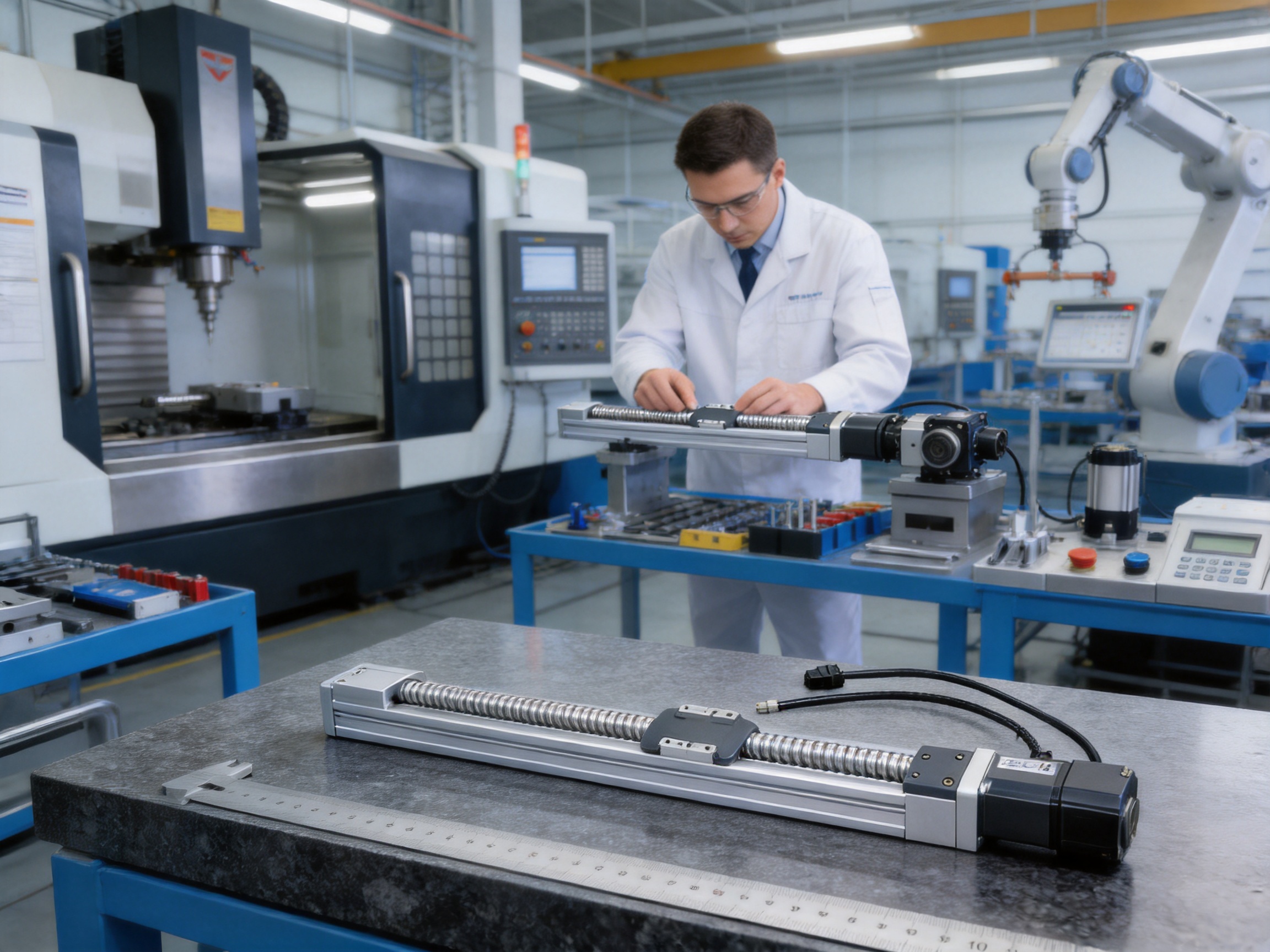
Begin by identifying the required travel distance. Select the nearest standard stroke from 50 mm to 800 mm, remembering to allow additional space for the overall body length, motor, cables, sensors, and machine guarding.
Next, determine the installation direction. Horizontal mounting generally allows the highest payload. Wall-mounted and vertical arrangements require additional analysis of gravity and moments. Ceiling-mounted inverted installation requires supplier review because the standard specifications do not apply.
Then select the ball screw lead. Choose the 5 mm lead when thrust and payload are the main priorities, the 10 mm lead when a balanced speed and force are required, and the 20 mm lead when rapid movement is more important than thrust.
Calculate the complete moving mass. Include the payload, bracket, tooling, cable carrier contents, sensors, and any attached components. Check both the direct payload rating and the static moment values. The center of gravity should be measured from the relevant guide reference locations.
Choose a motor orientation that matches the machine layout. Confirm the motor brand and driver model, and select a brake-equipped version for vertical applications when load holding is required. Review the sensor type and controller input compatibility before purchase.
Finally, consider the operating environment. Temperature, dust, moisture, chemical exposure, vibration, cleanliness, and required maintenance access can all influence the suitability of the standard module. Discuss special environmental requirements with the supplier before finalizing the design.
The stated repeatability is ±0.01 mm. Actual machine performance also depends on mounting rigidity, servo tuning, payload distribution, temperature, lubrication, and operating conditions.
Standard strokes range from 50 mm to 800 mm in 50 mm increments. The selected stroke affects the overall module length and weight.
The 20 mm lead provides the highest listed maximum speed of 1,000 mm/s. Its maximum horizontal payload is 3 kg and its rated thrust is 85 N.
The 5 mm lead provides the highest listed rated thrust of 341 N. It supports a maximum horizontal payload of 10 kg and a maximum vertical payload of 3 kg under the specified conditions.
Yes, the module can be used in vertical installations within the specified vertical payload ratings. A brake-equipped servo motor is recommended when the load must be held during power-off conditions.
Standard specifications do not apply to ceiling-mounted inverted use. The application should be reviewed with the supplier before this installation method is selected.
Listed options include Mitsubishi, Panasonic, and Delta 100 W AC servo motor configurations. Both non-brake horizontal and brake-equipped vertical versions are specified.
The listed external home sensor options include EE-SX672 with NPN output and FC-SPX303Z-2M with NPN output. Electrical compatibility should be confirmed with the machine controller.
The module uses a C7 ball screw with a nominal diameter of 12 mm. The available leads are 5 mm, 10 mm, and 20 mm.
The guaranteed service life is 10,000 km when the product is used normally and within the catalog specifications. Correct lubrication, alignment, loading, and maintenance are important to achieving the expected service life.
The module is designed primarily for compact, light-load precision applications. The 5 mm lead offers the highest payload within this product range, but applications involving heavy loads, large moments, or severe shock should be evaluated separately.
Confirm the stroke, ball screw lead, payload, speed, installation orientation, center of gravity, motor brand, brake requirement, motor orientation, sensor type, mounting method, environmental conditions, and controller compatibility.
The 0.01 mm High-Precision Light-Load Ball Screw Linear Module provides a compact and adaptable solution for precision linear motion. Its ±0.01 mm repeatability, C7 12 mm ball screw, high-rigidity W24 × H8.5 linear guide, 100 W AC servo motor configuration, and stroke range from 50 mm to 800 mm make it suitable for a broad range of light-load automation tasks.
The product’s three lead options allow users to prioritize thrust, balanced performance, or speed. Its horizontal, wall-mounted, and vertical installation possibilities support different machine structures, while multiple motor orientations help simplify mechanical integration. Compatibility with Mitsubishi, Panasonic, and Delta servo platforms further supports practical deployment in existing automation environments.
Compared with generic linear slides, the module offers the benefits of an integrated ball screw, guide, motor interface, sensor arrangement, and defined performance data. Compared with oversized industrial actuators, it provides a more space-efficient approach for applications that do not require heavy-load capacity.
The manufacturer strengthens this product offering through in-house research and development, advanced design software, high-precision CNC machining centers, core patents, industry-academic cooperation, and experience across electric cylinders, servo presses, robotic axes, linear motor modules, and motion simulation platforms. These capabilities support both standardized products and customized automation solutions.
For equipment manufacturers seeking compact precision motion, the most important step is to match the module configuration with the actual load, center of gravity, speed, mounting direction, and duty cycle. When selected and maintained within its specifications, this ball screw linear module can provide reliable positioning and stable long-term service for modern intelligent manufacturing equipment.
1. Product Technical Specification Sheet, 0.01 mm High-Precision Light-Load Ball Screw Linear Module.
2. Ball Screw Linear Motion Design Principles, engineering reference material for screw lead, thrust, speed, and efficiency selection.
3. Linear Guide Installation and Alignment Practices, industrial motion component engineering guidance.
4. AC Servo Motor and Drive Integration Guidelines, technical reference for motor sizing, braking, homing, and commissioning.
5. Precision Automation Equipment Design Methods, reference material for payload, center-of-gravity, moment, and repeatability evaluation.
6. Industrial Maintenance Practices for Ball Screw and Linear Guide Systems, guidance on lubrication, inspection, and service-life management.
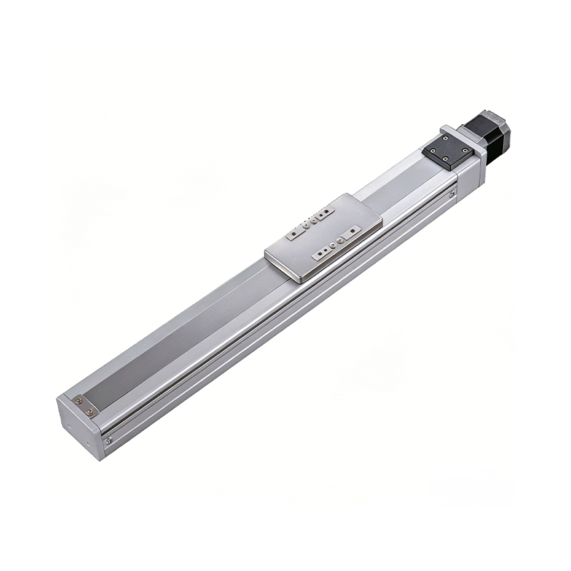 0.01mm High Precision Ball Screw Driven Rail-Embedded Linear Module
 Heavy Load Ball Screw Driven Rail-Embedded Linear Module
 110KG Load Long Stroke Rail-Embedded Linear Module
 Dual-Slider High Precision Rail-Embedded Linear Module
 Belt Driven Dust-Proof Rail-Embedded Linear Module
0.01mm High Precision Light Load Ball Screw Linear Module
Belt Driven Dust-Proof Rail-Embedded Linear Module
0.01mm High Precision Light Load Ball Screw Linear Module
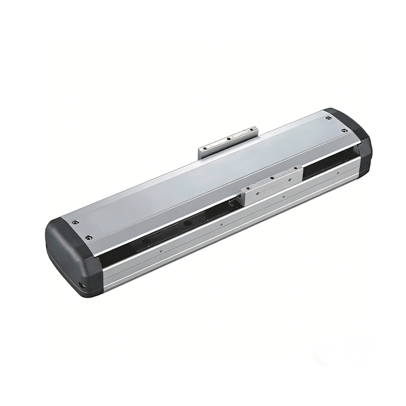 Ball Screw Linear Module with Built-in Sensor
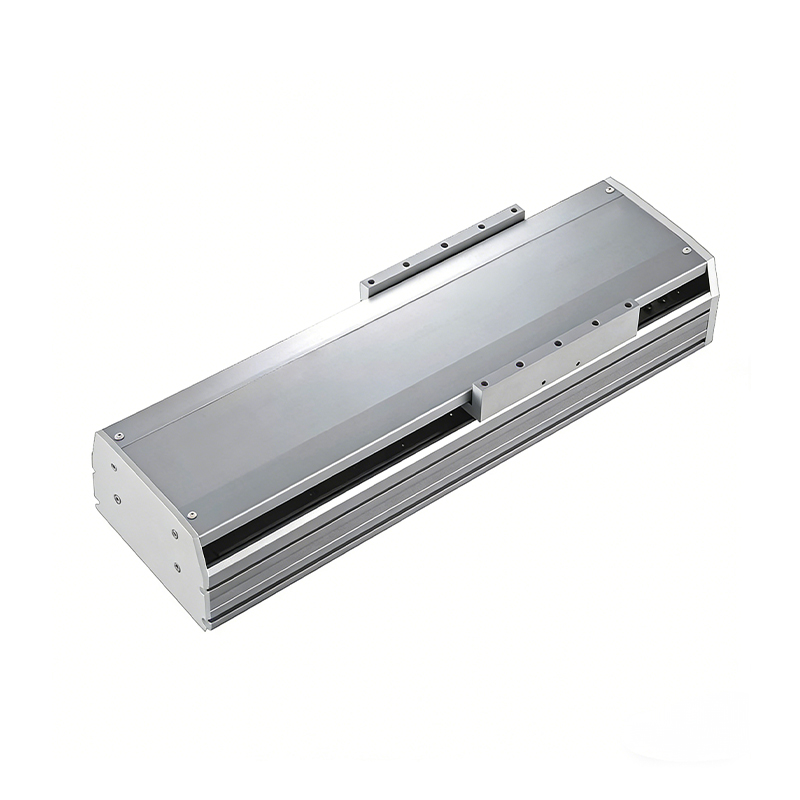 2000mm Long Stroke Ball Screw Linear Module
This 2000mm Long Stroke Ball Screw Linear Module is customized for large-range linear movement automation tasks, support...
READ MOREThis 2000mm Long Stroke Ball Screw Linear Module is customized for large-range linear movement automation tasks, support...
READ MOREThis 2000mm Long Stroke Ball Screw Linear Module is customized for large-range linear movement automation tasks, support...
READ MOREThis 2000mm Long Stroke Ball Screw Linear Module is customized for large-range linear movement automation tasks, support...
READ MORE
If you are interested in our products, please leave us a message. We look forward to providing you with
professional services!
Innovation and transcendence make factory intelligent manufacturing efficient and convenient!
+86 186 2508 0683
19962977901
sales@sz-tys.com
Building 5, Suzhou Mudu International Science and Technology Innovation Park, Jinfeng South Road, Suzhou City, Jiangsu Province, China
