


 English
 Français
 русский
 عربى
عربى Español
 Deutsch
Tel
+86 186 2508 0683

Heavy-duty industrial three-degree-of-freedom platforms are engineered to reproduce controlled angular and linear motion for demanding applications in research, industrial inspection, simulation, education, virtual reality, and advanced automation. Unlike basic positioning tables or general-purpose mechanical stages, these platforms coordinate multiple actuators through a unified control architecture. The result is a compact motion system capable of producing repeatable pitch, roll, and transverse displacement while supporting substantial payloads and maintaining stable operation over extended periods.
The heavy-duty industrial three-degree-of-freedom platform described in this article is designed for organizations that require more than simple movement. It combines electric-cylinder actuation, servo motor technology, EtherCAT communication, high-dynamic ball screw mechanisms, motion-control algorithms, and modular mechanical construction. Its configuration can be adapted to different loads, travel requirements, installation conditions, and application-specific motion profiles.
Manufactured by Suzhou Tongyousheng Electronic Technology Co., Ltd., the platform reflects the company’s broader capabilities in electric cylinders, linear motion modules, linear motor modules, servo presses, robotic axes, and multi-degree-of-freedom motion systems. The company integrates product research and development, mechanical design, software development, precision manufacturing, assembly, testing, and technical support to provide complete motion solutions rather than isolated mechanical components.
A three-degree-of-freedom platform is a motion system capable of controlling three independent movement variables. Depending on the selected configuration, these movements may include two angular axes, such as pitch and roll, together with a linear or transverse displacement axis. The exact movement combination can be customized according to the intended application. In simulation equipment, the platform may reproduce controlled attitude changes. In industrial inspection, it may position a large workpiece or sensor assembly. In education and research, it may provide a programmable demonstration of coordinated motion.
The platform uses several independently controlled electric cylinders or servo-driven linear actuators. These actuators are connected to a moving structure through fork hinges, flanges, or trunnion-type installation interfaces. By changing the extension or retraction of individual cylinders in a coordinated sequence, the control system generates the required platform pose and displacement.
This arrangement provides a practical alternative to systems based on hydraulic actuation or manually adjusted mechanical fixtures. Electric actuation offers clean operation, accurate digital control, easier integration with industrial communication networks, and reduced infrastructure requirements. It also allows the motion profile to be changed through software instead of requiring extensive mechanical modification.
The heavy-duty design is particularly important when the equipment must support large payloads, operate for long hours, or withstand repeated dynamic movement. The available product range covers effective loads from approximately 100 kg to 5,000 kg, depending on the configuration. The platform can also be developed with motor powers from 400 W to 22 kW, rated outputs from 1 kN to 150 kN, and stroke or range options selected for the application.
One of the most important advantages of this platform is its customization capability. Standard motion products are often limited by fixed dimensions, predetermined actuator capacities, and rigid software functions. Such limitations can create difficulties when a customer needs to install the platform inside an existing test structure, accommodate an unusual payload, or reproduce a specialized motion sequence.
The platform can be customized for three-degree-of-freedom and six-degree-of-freedom applications. Customization may address the mechanical layout, platform size, actuator stroke, load capacity, speed, installation interface, visual appearance, control mode, software functions, and communication method. This makes the equipment suitable for classrooms, laboratories, industrial production areas, inspection stations, simulation centers, and demonstration facilities.
Customization begins with a review of the customer’s operating conditions. The engineering team can assess the available installation space, required motion range, payload center of gravity, acceleration requirements, duty cycle, operating environment, and interface requirements. This information is then used to determine the appropriate electric-cylinder specifications, motor power, screw lead, structural dimensions, and control strategy.
For a research laboratory, the priority may be high repeatability and flexible software access. For an industrial inspection line, the priority may be load capacity, cycle time, and reliable integration with detection equipment. For a training or simulation platform, the priority may be smooth motion, user safety, and intuitive control. A configurable platform can address these different priorities without forcing every customer to purchase the same fixed design.
Heavy-duty performance depends on more than selecting a powerful motor. The frame, joints, electric cylinders, ball screws, bearings, mounting interfaces, servo drives, and control algorithms must work together as a complete system. The platform is therefore designed around the relationship between payload, actuator force, speed, structural stiffness, and motion accuracy.
Depending on the selected model, the product can accommodate effective loads ranging from approximately 100 kg to 5,000 kg. Rated output options extend from 1 kN to 150 kN, while motor power can range from 400 W to 22 kW. These broad ranges allow the system to be matched to both medium-sized test assemblies and large industrial equipment.
Load capacity is evaluated together with the position of the payload. A large object with a high center of gravity may generate greater overturning moments than a compact object of the same mass. For this reason, a reliable platform design must consider the load distribution, attachment points, movement direction, dynamic acceleration, and emergency stopping conditions.
The use of mechanical analysis and simulation tools supports this design process. Structural behavior can be reviewed before production, allowing engineers to optimize component dimensions, connection methods, and actuator placement. This approach helps reduce unnecessary weight while preserving stiffness and safety margins.
Precision is essential when a motion platform is used for testing, calibration, simulation, or automated inspection. Small errors in angle or displacement can affect test results, create inconsistent product evaluations, or reduce the realism of a simulation. The platform therefore combines accurate mechanical transmission with closed-loop servo control.
Reference performance data includes positioning accuracy of approximately 0.03 degrees for the angular axes and approximately 0.03 millimeters for the displacement axis. Repeat positioning accuracy can reach approximately 0.03 degrees for angular motion and 0.01 millimeters for linear movement, depending on the final design and operating conditions.
Angular motion ranges are available from approximately ±3 degrees to ±30 degrees. The corresponding reference speed is up to 50 degrees per second, with acceleration of approximately 100 degrees per second squared. The transverse displacement range can be configured from approximately ±10 millimeters to ±800 millimeters, with a reference speed of up to 1,000 millimeters per second and acceleration of up to 2.0 g.
These values are reference ranges rather than universal specifications for every platform. Actual performance depends on actuator selection, payload, stroke, structural configuration, motor and drive combination, control profile, and installation conditions. This configurable approach is an advantage because it allows performance to be optimized for the customer’s actual use rather than relying on a nominal specification that may not suit the application.
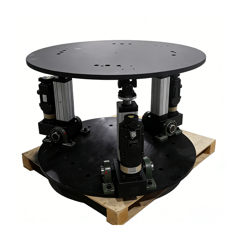
Heavy-Duty Industrial Three-Degree-of-Freedom Platform
The electric cylinder is the primary linear actuator used to generate controlled movement. It converts servo motor rotation into precise linear extension and retraction through a ball screw or related screw transmission mechanism. Compared with conventional pneumatic cylinders, an electric cylinder provides improved position control, programmable speed, flexible acceleration, and better suitability for synchronized multi-axis motion.
The available electric-cylinder configurations cover screw diameters from approximately 12 to 80 millimeters, lead values from approximately 5 to 32 millimeters, and effective stroke or range values from approximately 75 to 500 millimeters. The appropriate combination is selected according to required thrust, speed, resolution, load, and service life.
A smaller screw lead can support finer movement resolution and greater mechanical advantage, while a larger lead can provide higher linear speed under the same motor conditions. The selection must balance speed, force, thermal loading, efficiency, and positioning requirements. This is why the engineering process does not treat the lead, diameter, and motor as independent choices.
Strength verification is also important. Each electric cylinder must be assessed for axial force, buckling risk, bearing load, screw life, joint stress, and dynamic impact. Correct sizing improves stability and helps the platform maintain reliable performance during repeated high-frequency operation.
The platform adopts a high-dynamic ball screw mechanical design. Ball screws are widely used in precision motion systems because rolling contact reduces friction compared with sliding screw mechanisms. When correctly selected and lubricated, they can provide efficient power transmission, accurate positioning, and stable operation across repeated cycles.
Ball screw performance depends on screw diameter, lead, preload, support configuration, lubrication, alignment, load distribution, and operating speed. The design must also consider the possibility of vibration or resonance when the platform changes direction quickly. Mechanical simulation and practical testing are used to improve the relationship between actuator speed and platform response.
The screw transmission is integrated with servo motors and drives so that the control system can accurately regulate position, speed, and acceleration. This integration allows the platform to follow programmed motion trajectories smoothly instead of moving through abrupt or poorly coordinated steps.
The electric cylinders can be configured with front and rear fork hinges, flange connections, or trunnion-style installation structures. These interfaces provide flexibility when adapting the platform to different frames, payload structures, or customer-developed equipment.
Fork hinges can accommodate controlled angular changes at the connection point. Flange mounting can provide a firm and compact attachment where the surrounding structure supports direct bolting. Trunnion mounting can be useful when the cylinder must rotate around a defined axis during operation. Selecting the correct interface helps prevent excessive side loading and improves actuator life.
Mechanical installation is reviewed together with the motion geometry. The attachment locations determine the relationship between cylinder travel and platform angle. A well-designed geometry can provide the required range while avoiding unfavorable positions, excessive actuator force, or loss of mechanical advantage near the limits of travel.
The motion platform uses an EtherCAT bus control system. EtherCAT is designed for fast industrial communication and synchronized data exchange between the controller, servo drives, motors, and related devices. Its low-latency characteristics are valuable when several actuators must respond together to create accurate coordinated motion.
In a multi-axis platform, timing differences between actuators can create unwanted vibration, trajectory errors, or uneven loading. A high-speed fieldbus helps the system distribute control commands and collect feedback with consistent timing. This supports precise linkage between the individual electric cylinders.
EtherCAT also makes it easier to connect the platform with industrial controllers, inspection equipment, data acquisition systems, and customer-developed control terminals. The communication architecture can be adapted to different integration requirements, subject to the final system design.
The reference system response frequency is approximately 0 to 20 Hz. This range supports controlled motion profiles for simulation, inspection, research, and training applications. Low-latency communication helps the platform respond quickly to command changes while preserving smooth coordination between axes.
Fast response does not mean that every application should operate at the maximum available speed. The ideal motion profile depends on the payload, structural stiffness, actuator selection, safety requirements, and user comfort. The control system can be configured to prioritize smoothness, acceleration, accuracy, or responsiveness according to the application.
For scientific testing, the system may need to reproduce a precise waveform or trajectory. For an industrial station, it may need to complete repeated positioning cycles with minimal settling time. For a simulation application, it may need to create smooth motion without sudden changes that could affect the user. The same platform architecture can support these different operating modes through software configuration.
Coordinated multi-axis movement requires more than sending independent position commands to separate actuators. The controller must calculate how the desired platform pose relates to the required actuator positions. It must also account for geometry, limits, speed, acceleration, and feedback.
The platform control software uses optimized parallel algorithms and accurate modeling to support this process. The algorithms coordinate the actuators so that the moving platform follows the intended trajectory. They can also help reduce discontinuities between motion segments, avoid unnecessary actuator conflicts, and improve response during complex movement patterns.
Control software supports non-calibration operation in the standard system concept. After iterative optimization, the software is intended to simplify operation and reduce the need for complex manual procedures. Depending on the project, optional matching algorithms, special-effect modules, and customized functions can be added.
A major benefit for system integrators is the availability of secondary development interfaces. Customers can connect the platform with external control terminals, sensors, simulation software, data acquisition systems, or inspection equipment. This allows the platform to become part of a larger automation or research system.
Motion acquisition software supports linear programming of movement so that the platform can execute smooth trajectories. Operators can define position, angle, speed, acceleration, and timing parameters according to the application. The software is designed to be accessible to users who may not be specialist motion-control programmers.
For advanced users, development interfaces can support customized workflows. A research group may need to send real-time data from a test model. An inspection system may need to command a sequence of positions based on measurement results. A simulation center may need to connect the platform to a specialized visual or mathematical model. Flexible communication makes these integrations more practical.
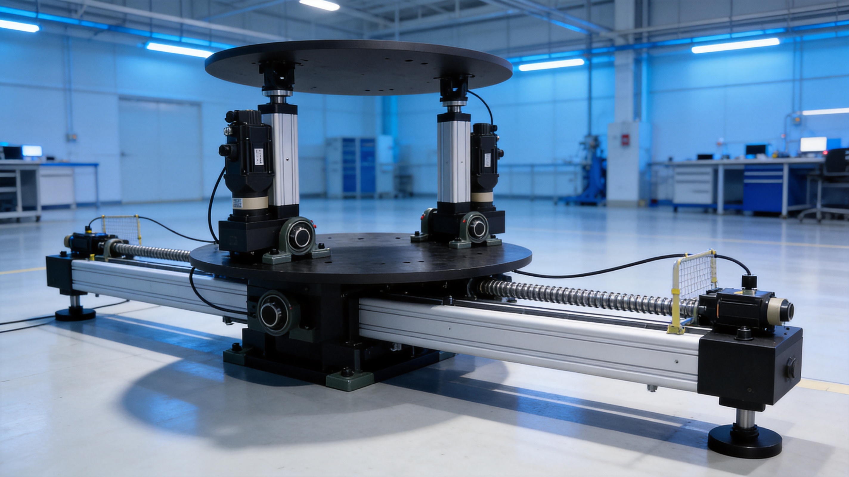
Suzhou Tongyousheng Electronic Technology Co., Ltd. operates as a high-tech enterprise integrating research and development, production, and sales. This integrated structure is important for complex motion products because mechanical hardware, electrical systems, servo drives, and software must be designed as a coordinated whole.
The company has developed products including electric cylinders, linear modules, linear motor modules, servo presses, robotic seventh axes, six-degree-of-freedom platforms, and multi-degree-of-freedom linkage systems. Experience across these product categories contributes to a broader understanding of force transmission, positioning, synchronization, servo control, and industrial integration.
Rather than treating the platform as a collection of purchased components, the engineering approach emphasizes the design of core hardware and software. The company develops platform control software and bus-type servo motor solutions while also selecting compatible motors, drives, screws, bearings, and structural components for each project.
Mechanical design is supported by professional engineering software, including PRO/E, MATLAB simulation, and mechanical analysis methods. Digital modeling allows engineers to study the platform’s geometry, actuator movement, potential interference, load distribution, and structural behavior before machining begins.
Simulation can be used to evaluate whether the planned structure meets the required angle, displacement, speed, and load conditions. It can also identify areas where the design may experience excessive stress or deflection. Corrective changes made at the design stage can improve production efficiency and reduce the risk of later modifications.
MATLAB-based analysis can support kinematic calculations, dynamic modeling, control development, and trajectory verification. Mechanical analysis can be used to review component strength and stability. Together, these tools help create a more scientific design process for high-load and high-precision applications.
The company uses high-precision CNC machining centers to manufacture important mechanical parts. CNC machining supports repeatable processing of mounting surfaces, actuator components, structural interfaces, and other precision parts. Accurate machining is essential because misalignment can increase friction, reduce positioning accuracy, and place additional stress on bearings or screw mechanisms.
Production quality depends on more than the machine tool itself. It also requires suitable material selection, process planning, fixture design, tool management, dimensional inspection, surface treatment, and assembly control. A consistent manufacturing process helps ensure that parts produced at different times can be assembled and serviced with reliable compatibility.
For a multi-axis motion platform, the relationship between components is especially important. The geometry of actuator mounts, platform joints, and frame interfaces affects the final kinematic performance. Precision manufacturing therefore supports not only individual part quality but also the accuracy of the complete system.
The platform adopts a modular structure. Core hardware is independently developed and produced, while the overall system is divided into functional modules that are easier to assemble, inspect, replace, and maintain. This design reduces the complexity of service work and can shorten downtime when a component requires replacement.
In conventional integrated equipment, the failure of a small component may require disassembling a large portion of the machine. A modular platform can simplify access to the relevant actuator, drive, control unit, or connection point. This is particularly valuable in industrial environments where the equipment may operate for long hours and maintenance windows may be limited.
Modularity also supports customization. The same platform architecture can be adapted with different electric cylinders, motor powers, mounting interfaces, structural dimensions, and software functions. This creates a practical balance between standardized engineering knowledge and application-specific configuration.
After machining, components must be assembled with attention to alignment, preload, joint movement, wiring, lubrication, and fastening. Electric cylinders and servo systems require coordinated commissioning so that position feedback, motor direction, limit settings, and control parameters operate correctly.
Testing should include no-load movement, loaded movement, positioning verification, repeatability checks, speed and acceleration assessment, communication testing, emergency stop testing, and extended operation. Where appropriate, the platform can be evaluated for drift during long-duration operation.
The reference data indicates that the platform system can be designed for continuous operation exceeding 12 hours, with the position drift of any individual cylinder limited to approximately 0.0025 meters under the stated reference conditions. Actual results depend on temperature, load, duty cycle, actuator selection, installation, and calibration. Long-duration testing helps identify thermal or mechanical factors that may affect stability.
Hydraulic systems can generate substantial force, but they usually require pumps, valves, hydraulic piping, reservoirs, fluid management, and additional noise-control measures. Electric-cylinder platforms can provide a cleaner and more compact alternative for applications where digitally programmable motion and precise positioning are priorities.
Electric systems also simplify installation because they do not require the same hydraulic infrastructure. Maintenance can be more straightforward because there is no hydraulic fluid leakage risk or fluid contamination management. In environments such as laboratories, classrooms, inspection areas, and indoor simulation centers, these benefits can be significant.
Hydraulic systems may remain appropriate for some extreme force or shock applications. However, for programmable multi-axis movement, servo synchronization, and integration with digital control networks, the electric architecture offers strong practical advantages.
Pneumatic cylinders are often economical for simple end-to-end movement, but their compressibility can make precise positioning and synchronized multi-axis control more difficult. Air preparation equipment, pressure fluctuations, and limited energy efficiency may also affect performance.
Electric cylinders provide direct control over position, speed, acceleration, and force-related parameters. They are more suitable for applications requiring repeatable trajectories, variable motion profiles, and precise stopping. The platform can therefore perform tasks that would be difficult to achieve with basic pneumatic actuation.
A standard linear stage generally provides one-axis translation. Several stages can be combined, but the resulting system may become tall, heavy, mechanically complex, or difficult to synchronize. A three-degree-of-freedom platform is designed from the beginning for coordinated movement in multiple axes.
The platform’s parallel architecture can distribute load across multiple actuators and create a compact motion envelope. It can also support combined angular and linear movement that is not practical with a simple stack of single-axis stages. This makes it attractive for attitude simulation, large-object inspection, and test systems requiring coordinated motion.
A fixed fixture may be reliable for one repetitive task, but it cannot easily adapt when the test angle, displacement, payload, or operating sequence changes. A programmable platform provides greater flexibility and can support multiple products or test conditions on the same equipment.
Software-based changes can reduce the need for mechanical redesign. Operators can update motion profiles, adjust speed limits, change test sequences, or connect new external equipment through available interfaces. This extends the useful life of the equipment as application requirements develop.
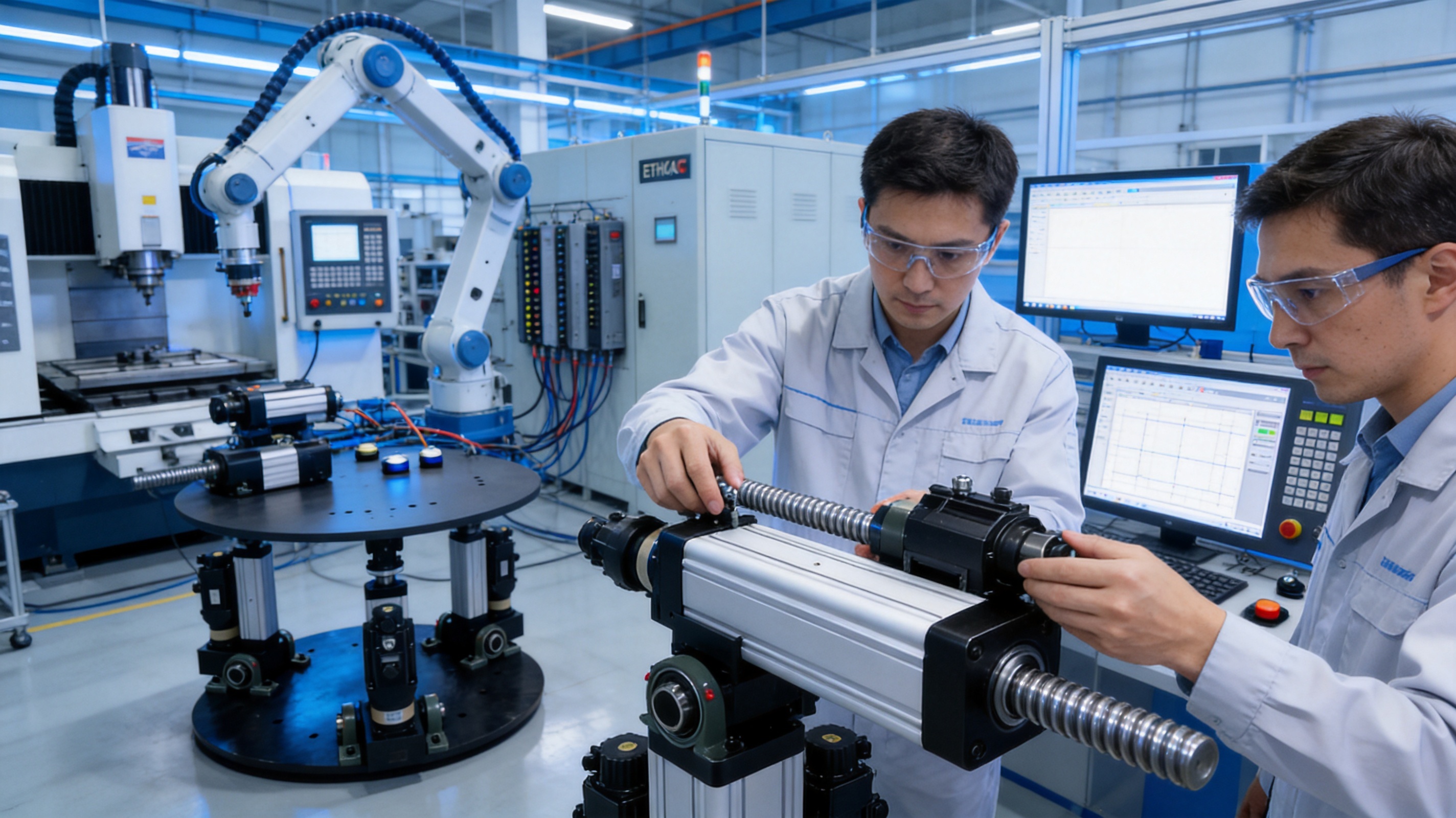
In industrial inspection, the platform can position a product, structure, sensor, camera, or measuring device at defined angles and displacements. Controlled motion can help inspect surfaces, joints, assemblies, electronic equipment, or mechanical systems under repeatable conditions.
Repeatability is especially valuable when comparing multiple products. If every item is inspected using the same trajectory and orientation, measurement results become easier to analyze. The platform can also be connected with detection systems, data acquisition devices, and customer-developed inspection software.
Research institutions can use the platform to study motion control, mechanical dynamics, structural behavior, robotics, automation, and simulation. The open development interfaces allow researchers to implement their own models, control strategies, or data-processing methods.
Because the system can be customized, a laboratory may specify unusual dimensions, a special payload interface, a particular actuator configuration, or an application-specific control mode. This is useful when off-the-shelf equipment cannot satisfy the research objective.
In educational environments, the platform can demonstrate kinematics, servo control, industrial communication, mechanical transmission, and coordinated motion. Students can observe how changes in actuator position create changes in platform angle or displacement.
The system can also be integrated into technical training programs covering automation, robotics, motion control, and intelligent manufacturing. Its modular architecture provides a practical example of how mechanical, electrical, and software technologies work together in an industrial system.
Motion simulation applications require smooth, coordinated, and responsive movement. The platform can be configured to reproduce selected motion cues for VR systems, simulation equipment, training devices, and interactive demonstration installations.
The most appropriate motion profile depends on the type of simulation. Some applications require limited angular motion with high smoothness. Others require greater linear displacement or faster response. Through customized actuators, mechanical geometry, algorithms, and software modules, the platform can be adapted to different simulation objectives.
The company’s experience with servo presses and electric cylinders also supports integration into production equipment. A three-degree-of-freedom platform may be used to position large assemblies, support a pressing or joining operation, or provide controlled movement between process stages.
In such applications, reliability, cycle time, force capacity, and communication with the production line are important. The EtherCAT architecture and modular equipment design can help connect the platform with other automation units, provided that the final system is engineered for the specific production process.
The following table summarizes the principal reference specifications supplied for the product family. These values are intended for technical evaluation and preliminary selection. Final specifications should be confirmed after reviewing the customer’s payload, motion profile, operating environment, and installation conditions.
| Item | Reference Specification | Engineering Significance |
|---|---|---|
| Degrees of freedom | Three; configurable angular and transverse displacement axes | Supports coordinated motion for simulation, inspection, and research |
| Pitch range | Approximately ±3° to ±30° | Defines the available angular attitude movement |
| Roll range | Approximately ±3° to ±30° | Supports controlled lateral tilt and orientation changes |
| Transverse displacement | Approximately ±10 mm to ±800 mm | Provides configurable linear positioning capability |
| Angular speed | Up to approximately 50°/s | Determines how quickly the platform can change angular position |
| Linear speed | Up to approximately 1,000 mm/s | Supports fast displacement where the load and structure permit |
| Angular acceleration | Approximately 100°/s² | Influences dynamic response and motion smoothness |
| Linear acceleration | Up to approximately 2.0 g | Supports rapid linear movement in suitable configurations |
| Angular positioning accuracy | Approximately 0.03° | Supports precision orientation and repeatable testing |
| Linear positioning accuracy | Approximately 0.03 mm | Supports accurate transverse positioning |
| Angular repeat positioning accuracy | Approximately 0.03° | Improves consistency between repeated angular cycles |
| Linear repeat positioning accuracy | Approximately 0.01 mm | Supports repeatable linear positioning |
| Effective load | Approximately 100 kg to 5,000 kg | Allows selection for medium and heavy payloads |
| Motor power | Approximately 400 W to 22 kW | Can be matched to force, speed, and duty-cycle requirements |
| Rated output | Approximately 1 kN to 150 kN | Defines the available actuator force range |
| Screw diameter | Approximately 12 mm to 80 mm | Influences strength, stiffness, and load capacity |
| Screw lead | Approximately 5 mm to 32 mm | Balances speed, resolution, and mechanical advantage |
| Stroke or range | Approximately 75 mm to 500 mm | Determines actuator travel and platform geometry |
| Communication | EtherCAT bus system | Provides synchronized industrial communication |
| Installation options | Fork hinge, flange, or trunnion | Supports adaptation to different mechanical structures |
| Average trouble-free working time | More than approximately 6,000 hours | Indicates suitability for extended industrial service |
| Power supply | Single-phase or three-phase | Allows adaptation to different facility power systems |
The first step in selecting a platform is to define the total payload, including fixtures, tools, sensors, cables, and any moving accessories. The center of gravity should also be identified because its location affects actuator force and platform stability.
A payload that is within the nominal mass range may still require a stronger configuration if its center of gravity is high or far from the platform center. Engineers should evaluate static weight, dynamic acceleration, overturning moment, emergency stopping force, and repeated cycle conditions.
Customers should specify the required pitch, roll, and linear displacement ranges independently. A large angular range may require additional joint movement or a different actuator arrangement. A long linear range may require a longer stroke, larger frame, or different screw configuration.
The requested range should include operating margins rather than using the absolute mechanical limit as the normal working position. Adequate margins can reduce wear, improve safety, and allow the control system to manage acceleration and deceleration more smoothly.
Speed and acceleration determine motor power, actuator force, control response, and structural loading. A platform intended for occasional laboratory experiments may require different specifications from one operating continuously on a production line.
Duty cycle information should include operating hours, cycle frequency, average movement distance, rest periods, ambient temperature, and expected maintenance intervals. This information helps engineers select the appropriate motor, screw, lubrication method, cooling arrangement, and control parameters.
Customers should identify whether they need standalone operation, external control, real-time data exchange, sensor integration, simulation software connection, or production-line communication. The available development interfaces and communication methods can then be matched to the application.
Software requirements may include trajectory programming, position tables, waveform reproduction, special effects, safety limits, data logging, operator permissions, and remote technical support. Defining these needs early can improve the efficiency of the final system design.
Long-term reliability is supported by modular construction, suitable component selection, software updates, and preventive maintenance. Operators should inspect mounting bolts, joints, wiring, protective covers, lubrication condition, abnormal noise, vibration, and actuator temperature at regular intervals.
Ball screws and moving joints require appropriate lubrication and contamination protection. The maintenance schedule should reflect the actual load, speed, operating environment, and duty cycle. Equipment used in dusty or high-cycle environments may require more frequent inspection than equipment used occasionally in a clean laboratory.
Servo motors and drives should be monitored for alarms, overload conditions, encoder errors, excessive temperature, or communication interruptions. Early detection can prevent secondary damage and reduce unexpected downtime.
The modular design makes it easier to replace key components when necessary. This can reduce maintenance time compared with systems in which components are deeply integrated and difficult to access. The company also continues to optimize core algorithms and update upper-level software, allowing customers to receive new functions and technical support over the service life of the equipment.
Motion-control technology develops continuously as new servo components, communication methods, algorithms, sensors, and software tools become available. A platform that can be updated and customized is more likely to remain useful as customer requirements change.
Suzhou Tongyousheng Electronic Technology Co., Ltd. invests in research and development and maintains cooperation with state-owned enterprises, defense technology institutions, universities, and industrial partners. These collaborations support the exchange of application knowledge and help connect practical engineering requirements with new product development.
The company’s product milestones include the development of linear modules, electric cylinders, servo presses, six-degree-of-freedom motion platforms, algorithmic control software, and multi-degree-of-freedom linkage systems. This product development history provides a foundation for creating complete motion solutions for intelligent manufacturing and Industry 4.0 applications.
Continuous iteration also benefits customers after delivery. Improvements to control algorithms, software interfaces, motion profiles, and diagnostic functions can extend the value of the installed equipment. Online software updates and technical support help customers maintain compatibility with evolving systems.
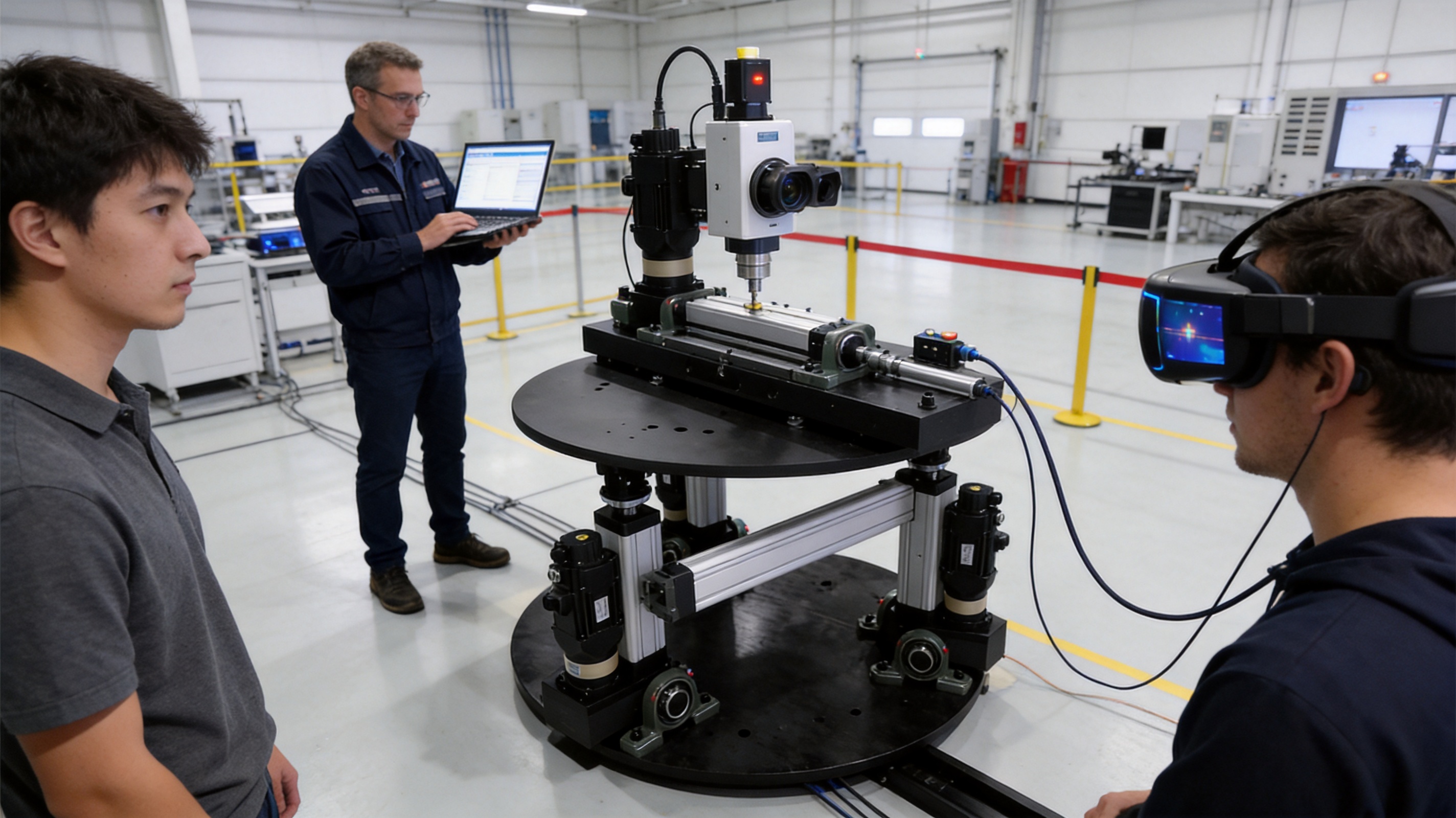
The platform is designed for three coordinated degrees of freedom. Depending on the configuration, these may include pitch, roll, and transverse linear displacement. The exact combination and range can be customized for the application.
Reference effective-load configurations range from approximately 100 kg to 5,000 kg. The final payload depends on the platform structure, actuator arrangement, center of gravity, speed, acceleration, and duty cycle.
Yes. Customization can address platform dimensions, actuator stroke, motor power, load capacity, motion range, installation method, appearance, software, communication interfaces, and special application functions. Three-degree-of-freedom and six-degree-of-freedom solutions can be developed according to customer requirements.
EtherCAT supports fast and synchronized communication between the controller, servo drives, and motors. This is useful when multiple actuators must move together with low latency and accurate timing.
Reference positioning accuracy is approximately 0.03 degrees for angular motion and approximately 0.03 millimeters for linear displacement. Reference repeat positioning accuracy is approximately 0.03 degrees for angular movement and 0.01 millimeters for linear movement. Final performance depends on the configuration and operating conditions.
It is designed for long-term industrial use, and the reference data indicates an average trouble-free working time of more than 6,000 hours. The system can also be designed for continuous operation exceeding 12 hours, subject to appropriate configuration, maintenance, and operating conditions.
The platform supports common industrial motor and drive brands, including ABB and Panasonic, depending on the project requirements. Motor selection is based on payload, speed, force, cost, duty cycle, and control compatibility.
Speed is influenced by motor speed, screw lead, transmission design, actuator stroke, load, acceleration limits, and control settings. A larger screw lead can increase linear speed under comparable conditions, while other factors determine whether the structure can safely use that speed.
Yes. The control system supports multiple communication methods and secondary development interfaces. This allows connection with control terminals, sensors, inspection equipment, data acquisition systems, and customer-developed applications.
The motion acquisition software is designed to be convenient to operate and supports linear motion programming. Although advanced integration may require engineering knowledge, routine operation can be simplified through configured software interfaces, motion parameters, and safety limits.
Maintenance includes inspection of joints, fasteners, wiring, lubrication, protective components, servo drives, and electric-cylinder operation. The modular structure makes it easier to access and replace key components, helping reduce downtime and maintenance cost.
Yes. Its programmable motion, modular construction, EtherCAT control, and development interfaces make it suitable for teaching kinematics, automation, servo control, industrial communication, robotics, and motion simulation.
The heavy-duty industrial three-degree-of-freedom platform is a versatile solution for applications requiring coordinated angular and linear motion, substantial load capacity, precise positioning, and programmable control. Its main strengths include customizable mechanical configurations, electric-cylinder actuation, high-dynamic ball screw transmission, EtherCAT communication, parallel motion algorithms, modular construction, and long-term software development.
Compared with hydraulic, pneumatic, fixed-fixture, and basic single-axis alternatives, the platform offers a strong combination of digital controllability, multi-axis coordination, installation flexibility, serviceability, and application adaptability. Its reference performance includes angular ranges up to approximately ±30 degrees, transverse displacement up to approximately ±800 millimeters, payload capacity up to approximately 5,000 kilograms, and positioning accuracy suitable for demanding industrial and research tasks.
The product is supported by an integrated engineering and manufacturing capability. Mechanical design, simulation, CNC machining, electrical integration, servo control, software development, assembly, testing, and technical support are combined to create complete motion equipment. This integrated approach helps ensure that the platform is not only capable of movement but also suitable for reliable use within larger automation, inspection, research, simulation, and intelligent manufacturing systems.
For customers seeking a long-term motion-control solution, the most important advantage is the ability to configure the platform around the real application. Load, range, speed, accuracy, communication, structure, and software can be evaluated together. This creates a more practical path to achieving stable, precise, and maintainable motion performance.
1. Product technical information for the heavy-duty industrial three-degree-of-freedom platform, including reference motion ranges, load capacity, accuracy, actuator specifications, and control architecture.
2. Internal product descriptions concerning modular platform design, electric-cylinder selection, EtherCAT communication, software functions, and customization services.
3. General engineering principles for servo motor sizing, ball screw transmission, multi-axis kinematics, structural analysis, and industrial motion control.
4. General technical literature on EtherCAT-based industrial communication and synchronized servo motion systems.
5. General technical literature on CNC machining, precision mechanical assembly, ball screw mechanisms, and preventive maintenance for industrial automation equipment.
6. Company information concerning research and development, manufacturing capabilities, automation product development, industrial partnerships, and intelligent manufacturing applications.
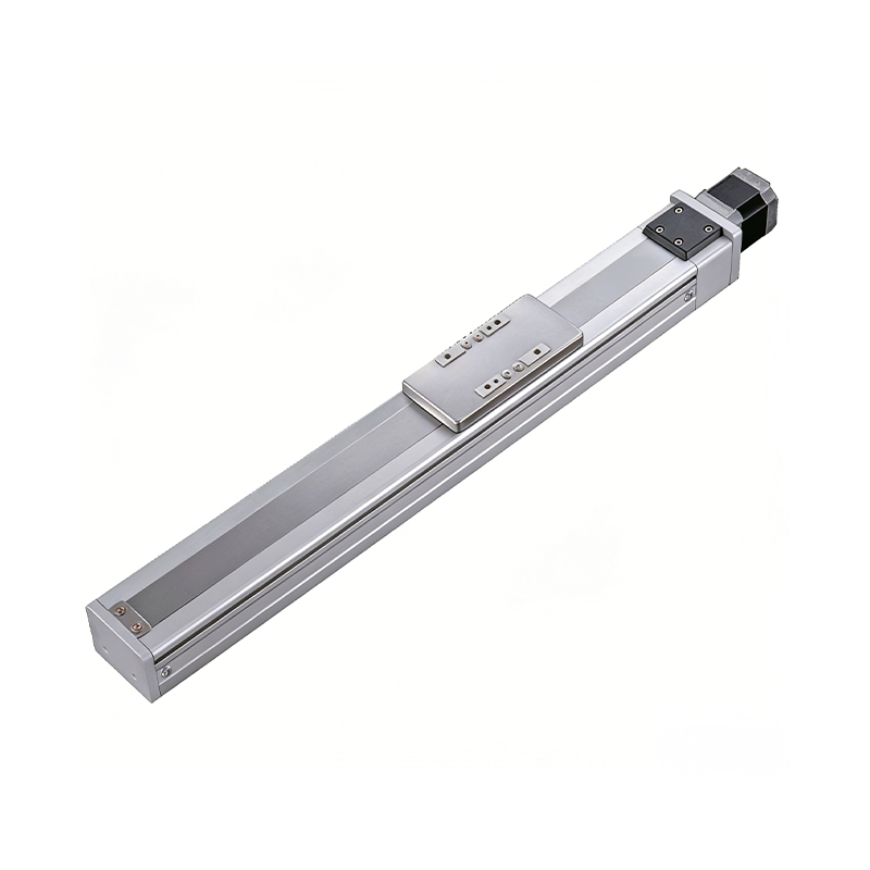 0.01mm High Precision Ball Screw Driven Rail-Embedded Linear Module
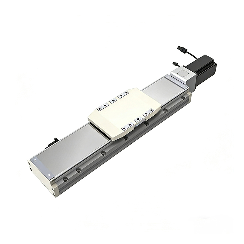 Heavy Load Ball Screw Driven Rail-Embedded Linear Module
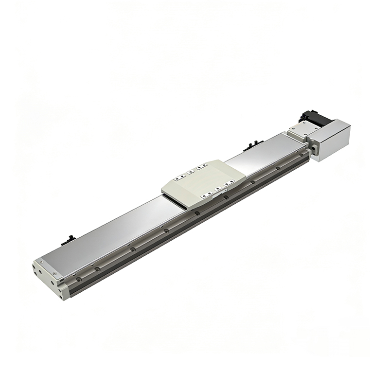 110KG Load Long Stroke Rail-Embedded Linear Module
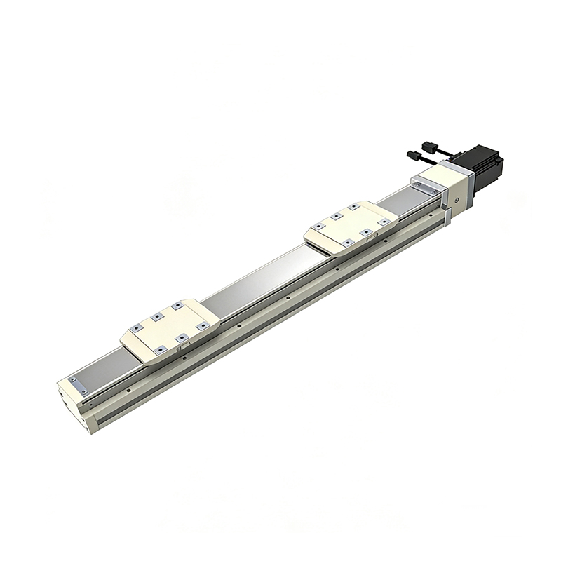 Dual-Slider High Precision Rail-Embedded Linear Module
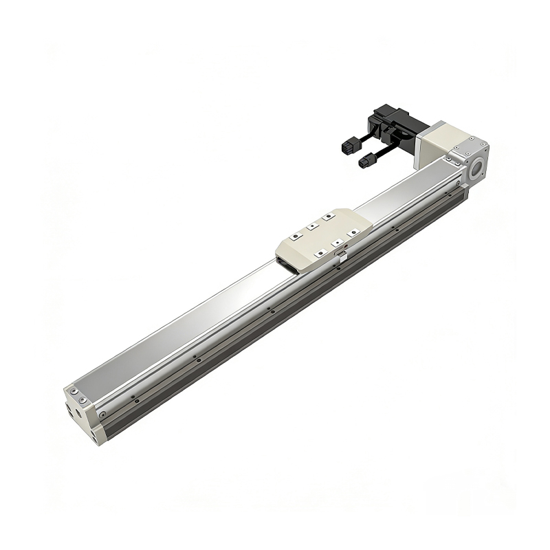 Belt Driven Dust-Proof Rail-Embedded Linear Module
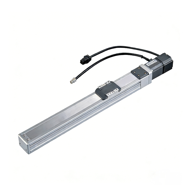 0.01mm High Precision Light Load Ball Screw Linear Module
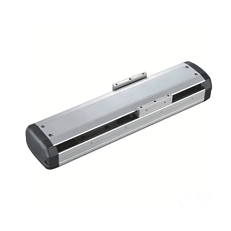 Ball Screw Linear Module with Built-in Sensor
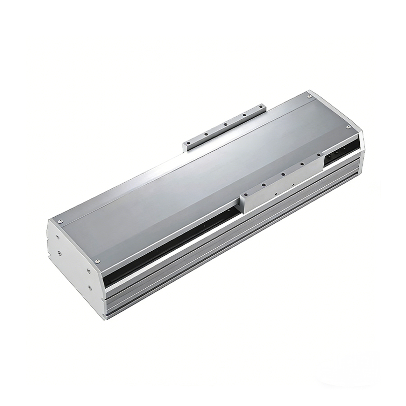 2000mm Long Stroke Ball Screw Linear Module
This 2000mm Long Stroke Ball Screw Linear Module is customized for large-range linear movement automation tasks, support...
READ MOREThis 2000mm Long Stroke Ball Screw Linear Module is customized for large-range linear movement automation tasks, support...
READ MOREThis 2000mm Long Stroke Ball Screw Linear Module is customized for large-range linear movement automation tasks, support...
READ MOREThis 2000mm Long Stroke Ball Screw Linear Module is customized for large-range linear movement automation tasks, support...
READ MORE
If you are interested in our products, please leave us a message. We look forward to providing you with
professional services!
Innovation and transcendence make factory intelligent manufacturing efficient and convenient!
+86 186 2508 0683
19962977901
sales@sz-tys.com
Building 5, Suzhou Mudu International Science and Technology Innovation Park, Jinfeng South Road, Suzhou City, Jiangsu Province, China
