


 English
 Français
 русский
 عربى
عربى Español
 Deutsch
Tel
+86 186 2508 0683

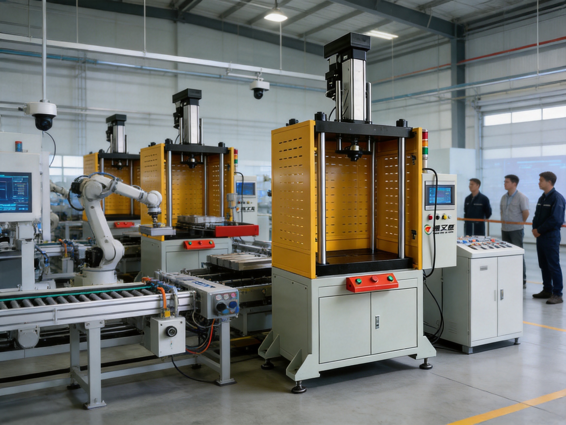
Modern manufacturing requires more than force. It requires controlled motion, repeatable positioning, measurable process data, operator protection, and a machine architecture that can be integrated into increasingly automated production environments. The Four Column Grid Guard Servo Press Machine is designed to address these requirements in one compact and adaptable solution. It combines a rigid four-column press structure, servo-controlled motion, force-displacement monitoring, an operator protection grid, and an intuitive human-machine interface for demanding industrial applications.
This servo press machine is suitable for press-fit assembly, punching, riveting, powder compacting, sealing, spring testing, stamping, and other controlled pressing operations. Its core value lies in the ability to manage the complete pressing cycle with precision. The machine can regulate pressing force, travel position, motion speed, pressure-maintaining time, and stopping conditions. These capabilities help manufacturers improve process consistency while reducing the risks associated with manual or less controllable mechanical pressing equipment.
Unlike conventional hydraulic presses that may depend on pressure fluctuations, oil systems, and complicated maintenance procedures, a servo press can directly control the relationship between motor movement, displacement, and applied force. This makes it suitable for production environments where quality depends on accurately controlling the entire press-fit or forming curve rather than simply reaching a target pressure.
The Four Column Grid Guard Servo Press Machine uses a four-column frame to support the pressing mechanism and guide the working movement. This structure distributes the pressing load through a stable framework and helps maintain alignment between the upper pressing assembly and the workpiece. The four-column arrangement is particularly useful for applications requiring balanced force distribution and repeatable vertical movement.
The grid guard provides a physical safety barrier around the working area. At the same time, its open and visible structure allows operators to monitor the process without completely obstructing the view of the tooling and workpiece. This balance between safety and visibility is valuable in workshops where operators must observe loading, tooling condition, component alignment, or abnormal movement during setup and production.
The machine is driven by a servo system that supports programmable movement and controlled pressing. Depending on the selected model, the pressure range extends from 1 kN to 300 kN. The broad model range allows the machine family to serve both relatively delicate assembly tasks and higher-load forming or compacting applications.
In addition to regulating maximum force, the system supports fine adjustment of travel, speed, and pressure-maintaining time. The available travel range extends from 200 mm to 500 mm depending on the model. Press-fit speeds can reach up to 35 mm/s on smaller models, while fast-forward and return speeds can reach up to 100 mm/s on many models. These settings allow the machine to combine rapid approach and return movements with a slower, more controlled pressing stage.
The machine is also equipped with an HMI panel that allows operators to set process parameters, monitor machine status, and review pressing conditions. This interface supports easier operation than systems that require extensive manual adjustment or external monitoring instruments.
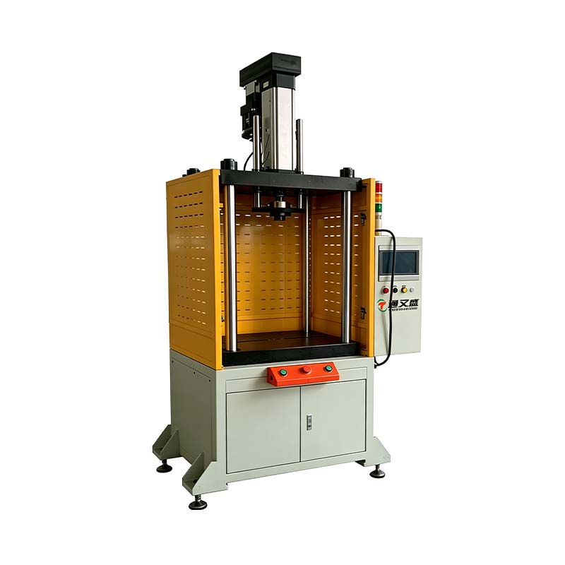
Four Column Grid Guard Servo Press Machine
A servo press converts programmed electrical motion into controlled mechanical pressing. Instead of relying only on a fixed mechanical stroke or a hydraulic pressure setting, the servo system can determine how the press moves throughout the cycle. This gives the machine greater flexibility when handling parts with different tolerances, materials, insertion forces, or final-position requirements.
Many assembly processes cannot be judged only by the final position of a component. A part may reach the correct position but still have an incorrect force curve. Excessive force can damage a component, while insufficient force can cause loose assembly, premature failure, or poor sealing. By monitoring force and displacement together, the servo press provides a more complete view of the process.
The equipment is assembled and measured as an integrated system. This design supports effective monitoring of the relationship between force and displacement during pressure loading, forming, joining, and other operations. It is especially useful when manufacturers need to confirm that every workpiece has experienced the required pressing conditions.
Servo control also enables multiple operating stages within a single cycle. For example, the machine may move quickly toward a workpiece, slow down before contact, apply a defined pressing speed, maintain a specified force or position, and then return after the process is complete. This type of sequence can improve cycle efficiency without sacrificing control during the critical pressing stage.
The programmable nature of the system also supports product changeover. Different workpieces can require different pressing depths, speeds, force limits, or holding times. These values can be configured through the control system rather than requiring major mechanical adjustments. As a result, the same machine can support several products or production variants.
The four-column design is one of the most important mechanical advantages of this servo press machine. A pressing system must resist bending, twisting, and uneven loading while maintaining alignment between the tool and the workpiece. The four-column frame creates a guided and supported structure around the working area.
In practical production, the benefits of a rigid structure include more stable tool movement, improved repeatability, and reduced risk of uneven contact. Balanced support is particularly valuable in applications such as powder compacting, sealing, spring testing, and press-fit assembly, where small deviations can influence product quality.
The structure also supports the use of different tooling arrangements. Depending on the application, users can install pressing heads, fixtures, dies, forming tools, riveting tools, or test adapters. The machine can therefore serve as a flexible production platform rather than a single-purpose press.
A stable frame also contributes to measurement reliability. Force and displacement data are more meaningful when the machine structure does not introduce excessive deflection or unwanted movement. By combining the four-column structure with servo control and process monitoring, the machine creates a stronger foundation for repeatable manufacturing.
Industrial pressing operations involve moving components, high mechanical forces, and potential pinch points. A suitable safety system is therefore essential. The grid guard creates a protected boundary around the active press area and helps reduce the possibility of accidental access during operation.
One advantage of a grid-style enclosure is visibility. Completely enclosed systems may provide strong protection but can make inspection and setup more difficult. A grid guard allows the operator to see the machine and tooling more easily during normal operation. This visibility helps with workpiece positioning, tooling inspection, and process observation.
The safety guard is particularly useful in workshops where the machine is operated near other automated equipment or integrated into a production line. It provides a clear physical separation between the operator and the pressing zone while preserving access for planned loading, unloading, and maintenance procedures.
Safety features should always be configured and validated according to the applicable regulations, risk assessment, and final machine installation. The grid guard is an important component of the protection strategy, but users should also consider emergency stops, control logic, access monitoring, safe operating procedures, and operator training.
The machine supports precise control of several process parameters. These include pressing force, stop position, loading time, pressing speed, return speed, and pressure-maintaining time. Each parameter can influence the result of the finished product.
Precise control of assembly size is important when a component must be inserted to a defined depth. The servo system can move to a programmed stop position and help produce a consistent final assembly dimension. This is valuable for bearings, bushings, connectors, shafts, pins, sleeves, and other components that depend on accurate insertion depth.
Precise stop-position control can also help prevent overtravel. In delicate assemblies, excessive movement may deform a housing or damage an internal component. A programmed position limit provides an additional layer of process control.
Accurate control of loading time and pressure is useful for materials that respond differently depending on how quickly force is applied. Sealing materials, elastomers, adhesives, spring components, and compacted powders may require a controlled loading profile rather than a sudden application of force.
Accurate control of pressure-maintaining force can improve the stability of forming and assembly processes. The machine supports a maximum pressure-maintaining time of up to 3,000 seconds according to the listed technical specifications. This broad range allows the equipment to accommodate short industrial cycles as well as longer holding processes.
Force-displacement monitoring is a central feature of the servo press. It enables manufacturers to examine how much force is required at each stage of movement and whether the relationship between force and position remains within an acceptable range.
In press-fit assembly, the force curve can reveal conditions that may not be visible from the outside. A sudden increase in force may indicate misalignment, an undersized opening, surface damage, contamination, or an incorrect component. An unusually low force may indicate a missing part, excessive clearance, insufficient interference, or a defective component.
In riveting, the force and displacement relationship can help assess whether the rivet has been properly formed. In sealing, the machine can help confirm that the required compression has been achieved. In spring testing, the recorded data can be used to evaluate load response and movement characteristics.
The minimum detection value is specified as 0.2 percent of the maximum pressure value. The pressure setting unit is 1 N, while the travel setting unit is 0.01 mm. These specifications demonstrate the machine’s focus on fine parameter adjustment and process sensitivity.
Data-based monitoring also supports quality traceability. Manufacturers can establish acceptable force and displacement windows and identify parts that fall outside those limits. When connected to a broader factory control system, the machine may support production records, statistical analysis, and process improvement programs.
Press-fit assembly is one of the primary applications for the machine. It can be used to insert bearings, bushings, shafts, pins, connectors, terminals, sleeves, and other components into housings or assemblies. The machine’s ability to control force and position is useful for preventing damage and ensuring consistent insertion depth.
More than 200 press-fit assembly projects are referenced for the equipment, with a stated first-pass yield of 99.2 percent. Actual performance depends on workpiece design, tooling, material variation, operator practice, and process conditions, but the reference indicates experience with a broad range of press-fit requirements.
The machine can be programmed for different phases of the cycle. It may approach the component quickly, reduce speed during contact, apply the required pressing force, stop at the target position, and hold or release according to the selected program.
The servo press can support punching applications where controlled force and precise movement are required. More than 150 punching applications are referenced, with hole diameter tolerance controlled within ±0.05 mm in the supplied application information.
Compared with basic punching arrangements, servo movement can provide greater flexibility in controlling the approach, punching stage, and return. This may help reduce unnecessary impact and improve the repeatability of the process, especially when the tooling and workpiece require a controlled motion profile.
Riveting requires a defined force and movement sequence to form the rivet correctly. Excessive force can damage the workpiece or create an irregular rivet head, while insufficient force may produce a weak joint. The machine’s programmable pressing cycle can be adapted to different rivet sizes and materials.
More than 200 riveting projects are referenced, with a riveting strength compliance rate above 98 percent. The force-displacement relationship can help manufacturers identify abnormal riveting behavior and improve consistency across production batches.
Powder compacting requires controlled pressure application and stable movement. The material may need to be compacted to a specific density, height, or shape. Uneven force or inconsistent stroke control can affect the final part.
The supplied information refers to more than 300 powder compacting cases and forming accuracy of ±0.02 mm. For powder processes, the final result also depends on powder characteristics, mold design, lubrication, filling consistency, and release conditions. The servo press provides the controlled mechanical movement required to support these process variables.
Sealing applications often depend on controlled compression. A seal that is compressed too little may leak, while excessive compression can damage the sealing element or create unnecessary assembly force. The machine can control the pressing position, force, and holding time required for a consistent seal.
More than 500 sealing solutions are referenced, with a leakage rate as low as 0.1 percent in the supplied material. As with all performance figures, final results should be validated using the customer’s actual components, sealing materials, fixtures, and test standards.
Spring testing requires accurate control of movement and force measurement. The machine can be used to compress or extend springs while recording the relationship between load and displacement. This supports evaluation of spring stiffness, working load, free length, compression behavior, and repeatability.
Professional spring testing is listed as one of the machine’s application areas. A controlled servo movement profile can help reduce test variation and make results easier to compare between samples.
The machine can also support selected stamping and forming operations. Servo control allows users to define the movement and force pattern required by the tooling. This may be helpful when a process requires a slower forming stage, a controlled dwell period, or a carefully managed return movement.
The correct model and tooling must be selected based on the material, forming force, die design, cycle time, and safety requirements. The available pressure range from 1 kN to 300 kN provides multiple options for different production needs.
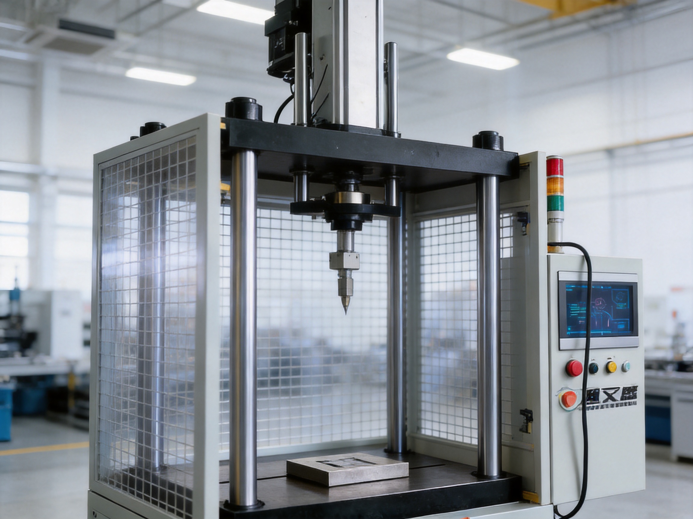
The product family covers small, medium, and higher-load applications. The model designation generally corresponds to the maximum pressure capacity in kilonewtons. The range includes TYSP-01, TYSP-05, TYSP-10, TYSP-20, TYSP-30, TYSP-50, TYSP-70, TYSP-100, TYSP-150, TYSP-200, TYSP-250, and TYSP-300.
| Model | Maximum Pressure | Maximum Travel | Press-Fit Speed | Fast Forward and Return Speed |
| TYSP-01 | 1 kN | 200 mm | 0–35 mm/s | 0–100 mm/s |
| TYSP-05 | 5 kN | 200 mm | 0–35 mm/s | 0–100 mm/s |
| TYSP-10 | 10 kN | 200 mm | 0–35 mm/s | 0–100 mm/s |
| TYSP-20 | 20 kN | 200 mm | 0–35 mm/s | 0–100 mm/s |
| TYSP-30 | 30 kN | 250 mm | 0–35 mm/s | 0–100 mm/s |
| TYSP-50 | 50 kN | 350 mm | 0–35 mm/s | 0–100 mm/s |
| TYSP-70 | 70 kN | 350 mm | 0–35 mm/s | 0–100 mm/s |
| TYSP-100 | 100 kN | 500 mm | 0–35 mm/s | 0–100 mm/s |
| TYSP-150 | 150 kN | 500 mm | 0–30 mm/s | 0–50 mm/s |
| TYSP-200 | 200 kN | 500 mm | 0–25 mm/s | 0–50 mm/s |
| TYSP-250 | 250 kN | 500 mm | 0–20 mm/s | 0–30 mm/s |
| TYSP-300 | 300 kN | 500 mm | 0–15 mm/s | 0–30 mm/s |
Every model supports a pressure setting unit of 1 N and a travel setting unit of 0.01 mm according to the listed specifications. As pressure capacity increases, maximum pressing and return speeds may decrease. This is a normal design consideration because larger machines must manage higher mechanical loads and greater moving mass.
The model selection should be based on more than maximum force. Users should evaluate the actual pressing force, required travel, tooling dimensions, workpiece size, cycle time, available installation space, desired data collection, and future product requirements. Selecting a machine with moderate reserve capacity can provide flexibility for process changes, but excessive oversizing may reduce sensitivity in low-force applications or increase investment unnecessarily.
The supplied dimensional information identifies several key parameters, including lead, diameter, stroke, and overall length, width, and height values. The dimensional schedule covers models from TYSP-05 through TYSP-70 and provides a reference for planning installation space, tooling access, and workcell layout.
| Model | Lead | D | S | Listed Length | Listed Width | Listed Height |
| TYSP-05 | 200 mm | 108 mm | 285 mm | 750 mm | 780 mm | 1880 mm |
| TYSP-10 | 200 mm | 108 mm | 285 mm | 750 mm | 780 mm | 1880 mm |
| TYSP-20 | 200 mm | 108 mm | 285 mm | 750 mm | 780 mm | 1950 mm |
| TYSP-30 | 200 mm | 208 mm | 385 mm | 800 mm | 950 mm | 1950 mm |
| TYSP-50 | 200 mm | 208 mm | 385 mm | 1000 mm | 1100 mm | 2100 mm |
| TYSP-70 | 200 mm | 308 mm | 385 mm | 1000 mm | 1100 mm | 2200 mm |
The original dimensional data contains repeated dimensional labels in its header. Before final engineering approval, buyers should confirm the meaning of each dimension, the reference points used for measurement, the working height, the guard footprint, the tooling envelope, and the service clearance. This verification is especially important when the press is being installed within an automated line or in a workshop with limited ceiling height.
A basic mechanical press may provide high production speed, but its motion profile is often determined by fixed mechanisms. A hydraulic press can provide strong pressing force, but control may depend on valves, pressure stability, and hydraulic components. The servo press provides programmable motion, allowing manufacturers to adjust speed and position according to the process.
This difference is important when one production line handles multiple workpieces. Programmable movement can reduce the need for frequent mechanical changes and make product changeovers more efficient.
Hydraulic equipment can require oil management, leak prevention, filtration, valve maintenance, and regular inspection of hoses and seals. A servo press does not depend on the same hydraulic circuit architecture. This can simplify routine maintenance and reduce concerns related to oil leakage or hydraulic contamination in certain production environments.
Maintenance requirements still exist. Servo motors, drives, mechanical transmission components, sensors, electrical connections, and tooling must be inspected. However, the maintenance profile can be more straightforward and cleaner for applications where hydraulic systems are not necessary.
The ability to monitor force and displacement gives the machine an advantage over presses that only indicate completion of a stroke. Manufacturers can establish quality criteria based on actual process behavior. This supports early identification of abnormal parts and helps reduce the risk of passing hidden assembly defects to later operations.
The model range from 1 kN to 300 kN gives users access to a broad selection of capacities. This makes it possible to choose a press for small precision assembly, medium-duty joining, or higher-load forming and compacting. A broad range also helps standardize equipment across multiple workshops or product lines.
The HMI panel allows operators to interact with the machine through a dedicated interface. Parameter setting, process selection, status monitoring, and troubleshooting can be organized in a more accessible manner than with a control cabinet that relies primarily on manual switches.
A well-configured HMI can also help reduce setup errors. Authorized users can define parameter limits, create product programs, and standardize machine operation across shifts.
The grid guard offers protection without creating a completely opaque enclosure. This is a practical advantage for applications that need frequent visual inspection or manual loading. The operator can observe the working zone while remaining separated from the active pressing movement.
The manufacturer is a high-tech enterprise integrating research and development, production, and sales. Its product portfolio includes electric cylinders, linear motion modules, linear motor modules, robotic seventh axes, servo presses, motion simulation platforms, and multi-degree-of-freedom systems.
This broad product background is relevant to the servo press because press equipment increasingly depends on coordinated motion, electric actuation, digital control, and mechanical integration. Experience with related motion products can support the development of compact drive systems, precision transmission structures, control algorithms, and automation interfaces.
The company maintains an experienced research and development team and uses advanced design software for product development. Three-dimensional mechanical design, motion analysis, component selection, and digital engineering tools can help engineers evaluate the structure before manufacturing. This approach supports better coordination between the frame, transmission mechanism, servo system, sensors, guarding, and HMI.
High-precision CNC machining centers are used in the company’s manufacturing capabilities. CNC machining supports accurate production of structural and transmission components and can help maintain dimensional consistency across batches. For a servo press, accurate machining is important because alignment, fit, guide geometry, mounting surfaces, and tool interfaces all influence performance.
The company also has a portfolio of core patents. Patented technologies may cover elements of motion systems, control methods, mechanical structures, or integrated automation solutions. Intellectual property is not a substitute for application validation, but it demonstrates an ongoing focus on engineering development and product differentiation.
The organization collaborates with state-owned enterprises, defense technology institutions, and leading universities. These relationships can contribute to the development of advanced motion control, testing methods, structural design, and specialized automation systems. Collaboration between industry, academia, and research institutions is particularly valuable for products that require both practical manufacturing knowledge and advanced engineering analysis.
The company was established in 2013 and has continued to expand its product development and manufacturing capabilities. Its development milestones include linear modules, electric cylinders, servo presses, six-degree-of-freedom motion platforms, algorithmic control software, and multi-degree-of-freedom platform linkage systems.
A reliable servo press depends on the quality of its entire production chain. The frame must be manufactured with appropriate rigidity and dimensional accuracy. Transmission components must be correctly assembled and adjusted. Servo drives must be configured to match the motor and mechanical load. Sensors must be mounted securely and calibrated. The safety guard and control logic must work together correctly.
The use of precision CNC machining centers supports consistency in structural components. Controlled machining can help reduce dimensional variation in mounting faces, guide supports, bearing seats, and tooling interfaces. After machining, assembly and measurement are important for confirming alignment and movement quality.
Testing should cover no-load movement, rated-load operation, positioning accuracy, force response, emergency stop behavior, HMI functions, and guard-related safety conditions. Application-specific validation may include force-displacement testing, repeatability testing, cycle testing, leakage testing for sealing applications, or strength testing for riveting applications.
The application experience listed for press-fit assembly, punching, riveting, powder compacting, sealing, and spring testing helps support a practical engineering approach. Each application has different process risks, and experience across multiple sectors can improve the ability to configure tooling, sensing, motion profiles, and quality limits.
Manufacturing quality also depends on documentation. Equipment drawings, electrical diagrams, parameter lists, maintenance instructions, replacement part information, and operating procedures help customers install and use the machine correctly. Clear documentation is especially valuable when the press is integrated with feeders, robots, conveyors, vision systems, or factory data networks.
The Four Column Grid Guard Servo Press Machine can serve as a standalone workstation or as part of an automated production cell. In a standalone arrangement, an operator may load and unload components while the machine executes the programmed cycle. In an automated line, robots or linear motion modules can transfer workpieces to and from the press.
The manufacturer’s experience with electric cylinders, linear motion modules, linear motor modules, and robotic seventh axes provides a foundation for broader automation integration. These products can be used in material handling, fixture positioning, tool changing, workpiece transfer, or coordinated multi-axis movement.
A production cell may include a feeder, a vision inspection system, the servo press, a marking unit, and an unloading robot. The press can perform the controlled joining or forming operation while the surrounding equipment handles logistics and inspection. This arrangement helps reduce manual handling and supports a more consistent process flow.
For integration, engineers should define communication protocols, input and output signals, cycle-start conditions, machine-ready status, fault signals, safety interlocks, workpiece-present confirmation, and quality-result outputs. These details help ensure that the press can communicate effectively with the line controller.
Data integration can also support manufacturing execution systems and quality databases. Pressing force, displacement, cycle time, product identifier, and pass-fail result may be recorded for traceability. The exact data architecture depends on customer requirements and the selected control configuration.
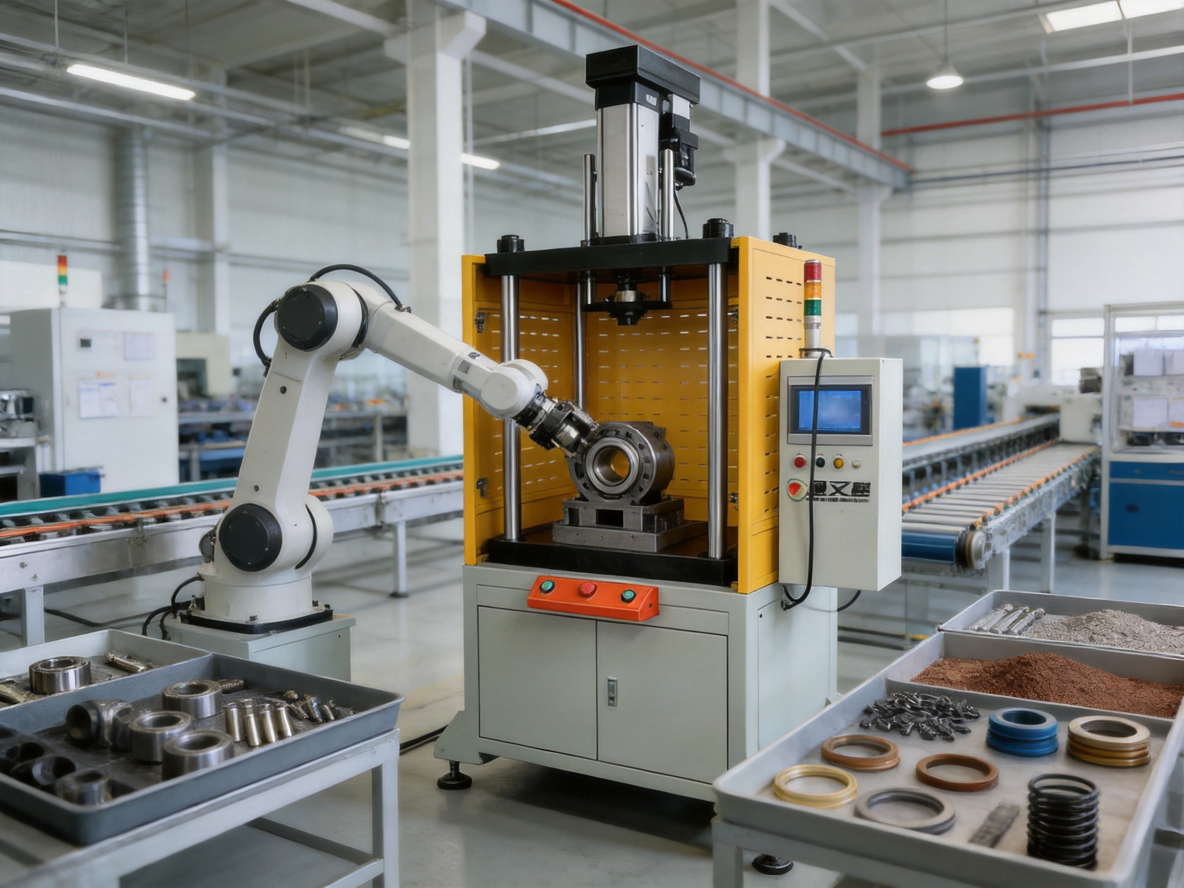
Before installation, the customer should confirm floor loading, machine access routes, power supply, grounding, working space, ventilation, lighting, and safety zones. The four-column structure and grid guard require sufficient clearance for operation and maintenance.
Tooling should be designed to distribute force correctly and maintain alignment with the press axis. Fixtures must hold the workpiece securely without obstructing the guard or interfering with sensors. The tooling design should also allow convenient loading, unloading, cleaning, and inspection.
During commissioning, engineers should verify the direction of movement, travel limits, force readings, position readings, emergency stop performance, guard conditions, HMI settings, and programmed speed profiles. Initial production trials should use conservative settings until the process window has been confirmed.
Routine maintenance may include checking fasteners, inspecting tooling, cleaning the working area, reviewing cable condition, confirming sensor mounting, and examining the mechanical transmission for unusual noise or vibration. Operators should monitor changes in cycle behavior, force curves, and positioning performance.
Preventive maintenance intervals should be established according to duty cycle, load, environment, and manufacturer recommendations. Applications involving dust, powder, oil, or high cycle counts may require more frequent cleaning and inspection. Any abnormal force increase, inconsistent stopping position, or unexpected vibration should be investigated before continued production.
The first step in selecting a model is to identify the required maximum pressing force. This should be based on measured process data or engineering calculations rather than an assumption based only on the workpiece size.
The second step is to define the required travel. The selected stroke should accommodate the workpiece, tooling, loading method, and safety clearance. A longer stroke may provide flexibility, but it can also influence machine height and cycle time.
The third step is to define the required force and displacement accuracy. Low-force assembly and testing may require a smaller-capacity model with suitable sensitivity, while forming or compacting may require a higher-capacity model with greater structural reserve.
The fourth step is to review the required speed profile. The machine may need rapid approach and return to achieve a short cycle time, while the pressing stage may need a lower speed for quality control. The listed speed ranges should be compared with the actual process requirements.
The fifth step is to examine tooling and workcell dimensions. Users should confirm table size, working height, press opening, guard footprint, loading direction, and access for maintenance.
The final step is to define quality monitoring requirements. If the process requires force-displacement evaluation, acceptable curve limits, data storage, barcode association, or communication with a production system, these requirements should be included during technical discussions.
The economic value of a servo press is not limited to the purchase price. A controlled press can influence labor requirements, scrap rate, rework, production consistency, maintenance, and product quality. When the process is sensitive to force or position, preventing a small number of defective assemblies may provide significant savings.
Improved first-pass yield can reduce repeated processing and inspection. More consistent pressing can reduce the risk of hidden defects that may appear during field use. Programmable recipes can shorten product changeovers and reduce the time required to adjust mechanical settings.
The machine can also help standardize production across shifts. Once a validated process program has been established, operators can follow defined settings rather than relying entirely on experience or manual judgment. This supports repeatability and simplifies training.
For companies expanding automation, the press can provide a foundation for future integration. It can begin as a manually loaded machine and later be connected to robots, conveyors, vision systems, and production data networks. This scalability can help manufacturers adopt automation in stages.
It is an electrically controlled pressing machine that uses a four-column structural frame and a servo-driven mechanism to regulate force, travel, speed, and holding time. The four-column structure supports stable pressing, while the servo system enables programmable and repeatable motion.
The grid guard separates the operator from the active pressing area and helps reduce access to moving parts during operation. Its open design also preserves visibility for setup, inspection, and process observation. The final safety configuration should be validated according to the installation risk assessment and applicable regulations.
The listed model range extends from 1 kN to 300 kN. Available models include TYSP-01, TYSP-05, TYSP-10, TYSP-20, TYSP-30, TYSP-50, TYSP-70, TYSP-100, TYSP-150, TYSP-200, TYSP-250, and TYSP-300.
The machine can serve industrial automation, automotive component production, electronics assembly, appliance manufacturing, hardware production, sealing operations, spring testing, powder forming, and general precision assembly. The correct application depends on the selected model, tooling, force requirement, and process conditions.
Yes. Press-fit assembly is one of its principal applications. It can control insertion force, travel, speed, stopping position, and holding conditions. These capabilities are suitable for bearings, bushings, shafts, pins, connectors, sleeves, and other interference-fit components.
Yes. The machine is designed to monitor the relationship between force and displacement during pressing, loading, forming, riveting, sealing, and testing. The listed minimum detection value is 0.2 percent of the maximum pressure value.
The listed travel setting unit is 0.01 mm. The maximum travel varies by model, ranging from 200 mm to 500 mm in the supplied technical specifications.
Press-fit speed ranges from 0–35 mm/s on smaller models and decreases on higher-capacity models. Fast-forward and return speed can reach 0–100 mm/s on many models, with lower maximum values on the largest models. Actual cycle time depends on travel, force, tooling, workpiece handling, and the programmed motion profile.
Yes. The machine can control compression position, pressing force, and pressure-maintaining time, which are important for sealing. The supplied application information references more than 500 sealing solutions and a leakage rate as low as 0.1 percent. Customer-specific testing is necessary to confirm final performance.
Yes. It can be configured as a standalone workstation or integrated into an automated cell. Integration may include robotic loading and unloading, conveyors, feeders, vision systems, linear motion modules, and factory control systems.
Users should consider required force, maximum travel, press-fit speed, cycle time, workpiece size, tooling design, desired measurement accuracy, installation space, safety requirements, and future production expansion. Selecting the correct capacity and tooling is essential for stable performance.
The servo press offers programmable movement, precise position control, force-displacement monitoring, and reduced dependence on hydraulic components. A hydraulic press may remain suitable for certain very high-force or specialized applications, but the servo design is advantageous when motion flexibility, cleanliness, repeatability, and process data are important.
The manufacturer’s capabilities include research and development, precision manufacturing, automation equipment production, motion control technology, servo press development, and application engineering. Support may include model selection, tooling coordination, process parameter configuration, integration planning, and technical documentation.
The Four Column Grid Guard Servo Press Machine is designed for manufacturers that require more than basic pressing force. It combines a stable four-column structure with programmable servo motion, force-displacement monitoring, an HMI operating system, and a visible grid guard. This combination supports safe, accurate, and repeatable production across press-fit assembly, punching, riveting, powder compacting, sealing, spring testing, stamping, and forming applications.
Its model range from 1 kN to 300 kN gives users flexibility when matching equipment to different process loads. Fine setting units for pressure, travel, and speed support detailed process development, while the maximum pressure-maintaining time of up to 3,000 seconds accommodates a wide variety of applications.
The manufacturer strengthens the product through in-house research and development, advanced design software, high-precision CNC machining centers, patents, application experience, and cooperation with industrial and academic organizations. Its wider expertise in electric cylinders, linear motion modules, linear motor modules, robotic axes, and motion platforms also supports the development of integrated automation solutions.
For manufacturers pursuing higher first-pass yield, improved traceability, safer operation, and greater production flexibility, this servo press provides a strong platform. Correct model selection, tooling design, safety validation, and process commissioning remain essential, but the machine’s architecture offers a practical foundation for modern intelligent manufacturing.
1. Product technical information for the Four Column Grid Guard Servo Press Machine, including model range, pressure capacity, travel, speed, and pressure-maintaining specifications.
2. Application information covering press-fit assembly, punching, riveting, powder compacting, sealing, and spring testing.
3. Manufacturer-provided dimensional data for TYSP series servo press models.
4. Manufacturer company profile describing research and development, precision CNC machining, patented technologies, and automation product capabilities.
5. General principles of servo press force-displacement monitoring and programmable motion control in industrial automation.
6. General industrial safety principles for guarded pressing equipment, operator protection, emergency stopping, and machine risk assessment.
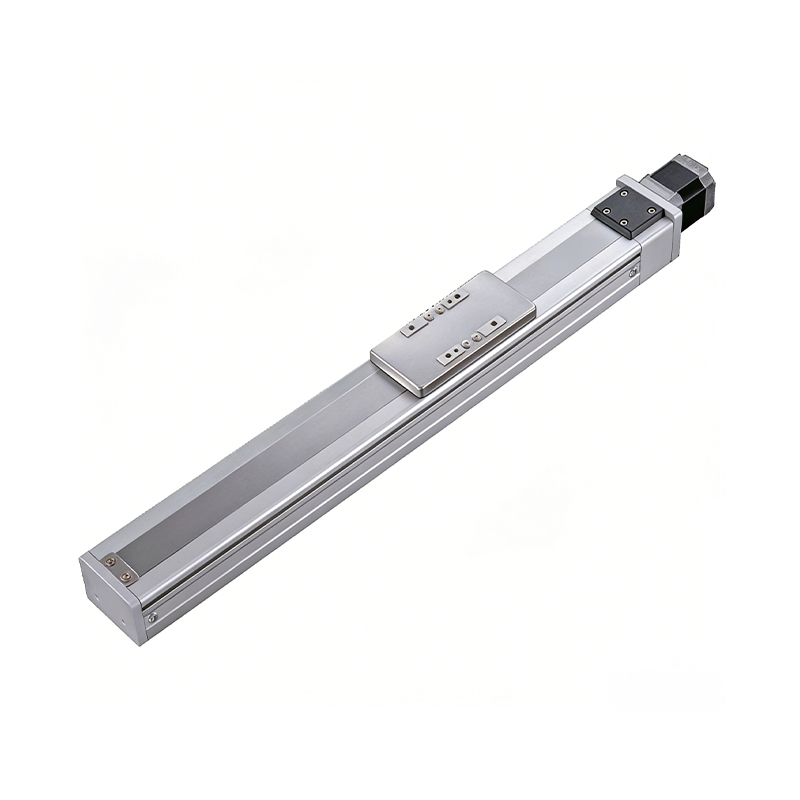 0.01mm High Precision Ball Screw Driven Rail-Embedded Linear Module
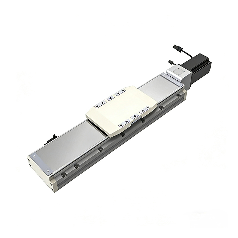 Heavy Load Ball Screw Driven Rail-Embedded Linear Module
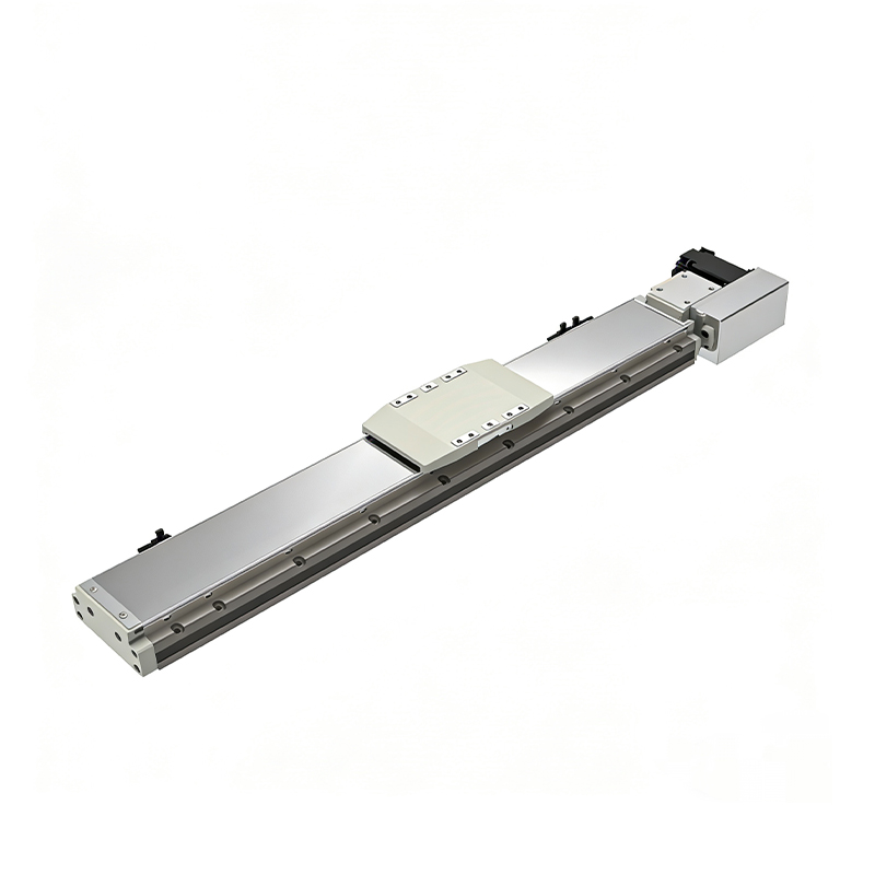 110KG Load Long Stroke Rail-Embedded Linear Module
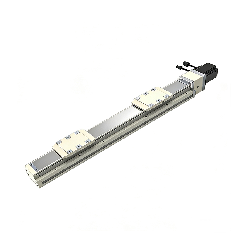 Dual-Slider High Precision Rail-Embedded Linear Module
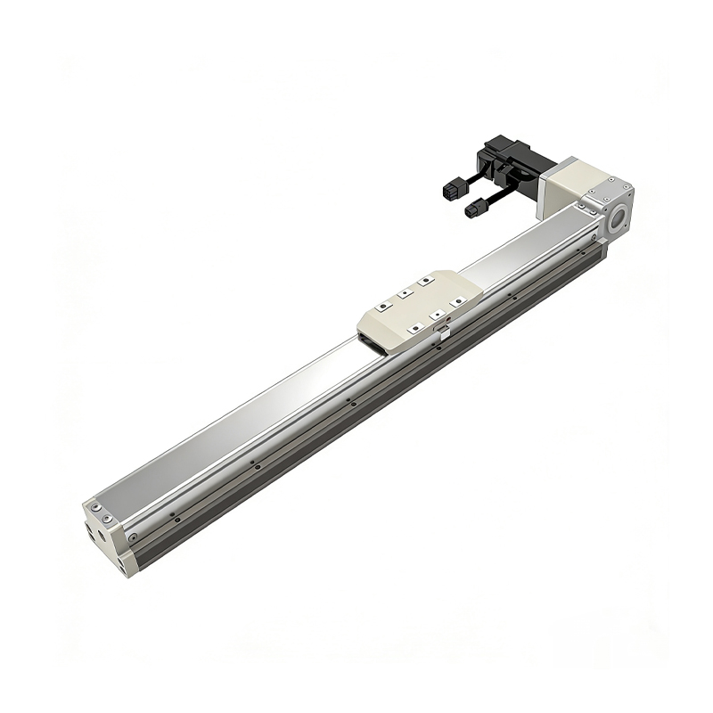 Belt Driven Dust-Proof Rail-Embedded Linear Module
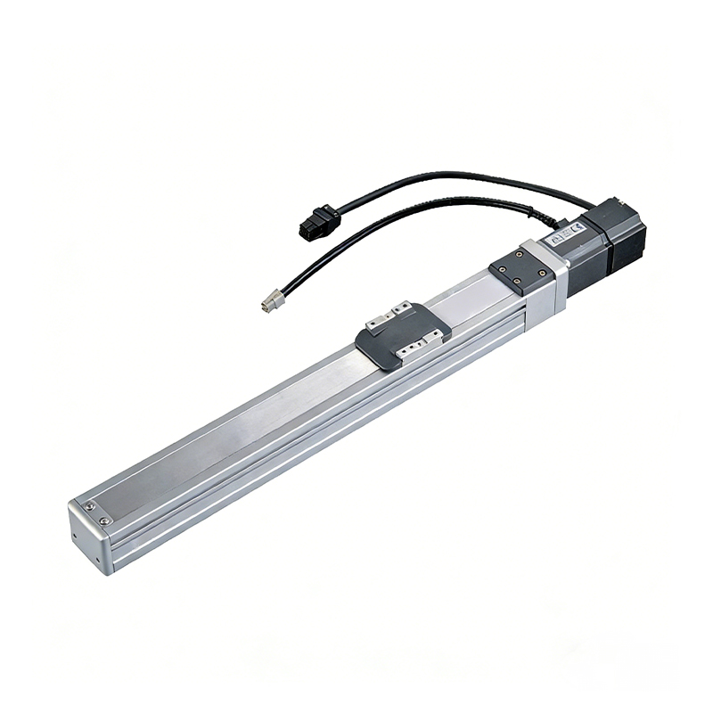 0.01mm High Precision Light Load Ball Screw Linear Module
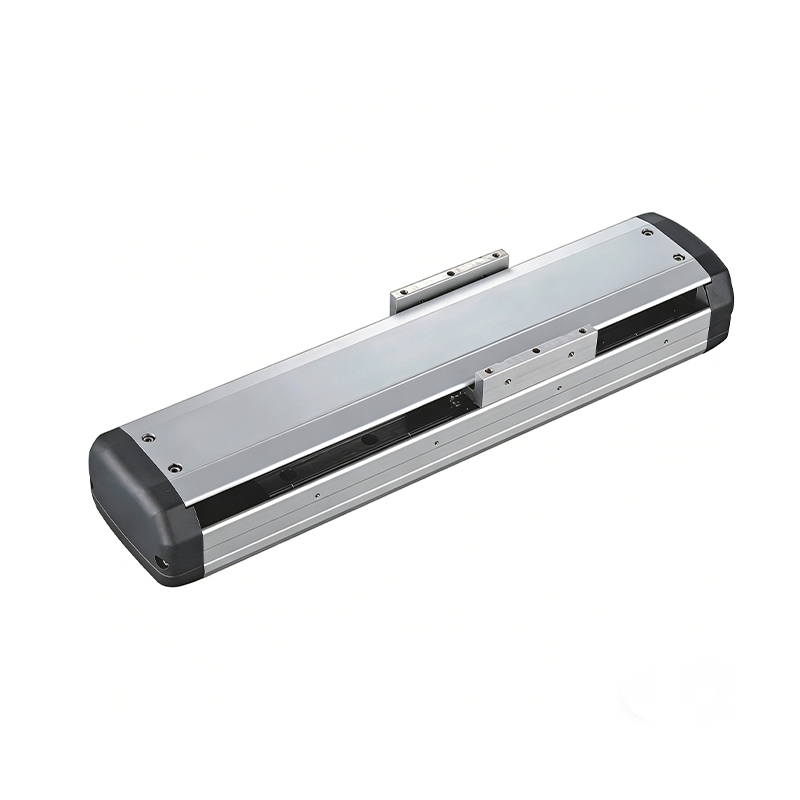 Ball Screw Linear Module with Built-in Sensor
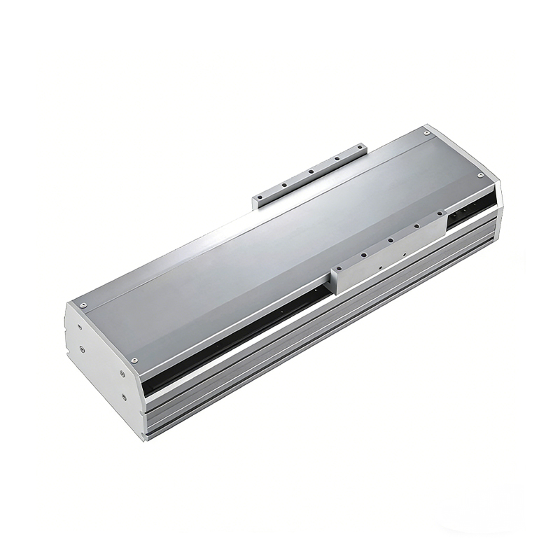 2000mm Long Stroke Ball Screw Linear Module
This 2000mm Long Stroke Ball Screw Linear Module is customized for large-range linear movement automation tasks, support...
READ MOREThis 2000mm Long Stroke Ball Screw Linear Module is customized for large-range linear movement automation tasks, support...
READ MOREThis 2000mm Long Stroke Ball Screw Linear Module is customized for large-range linear movement automation tasks, support...
READ MOREThis 2000mm Long Stroke Ball Screw Linear Module is customized for large-range linear movement automation tasks, support...
READ MORE
If you are interested in our products, please leave us a message. We look forward to providing you with
professional services!
Innovation and transcendence make factory intelligent manufacturing efficient and convenient!
+86 186 2508 0683
19962977901
sales@sz-tys.com
Building 5, Suzhou Mudu International Science and Technology Innovation Park, Jinfeng South Road, Suzhou City, Jiangsu Province, China
