


 English
 Français
 русский
 عربى
عربى Español
 Deutsch
Tel
+86 186 2508 0683

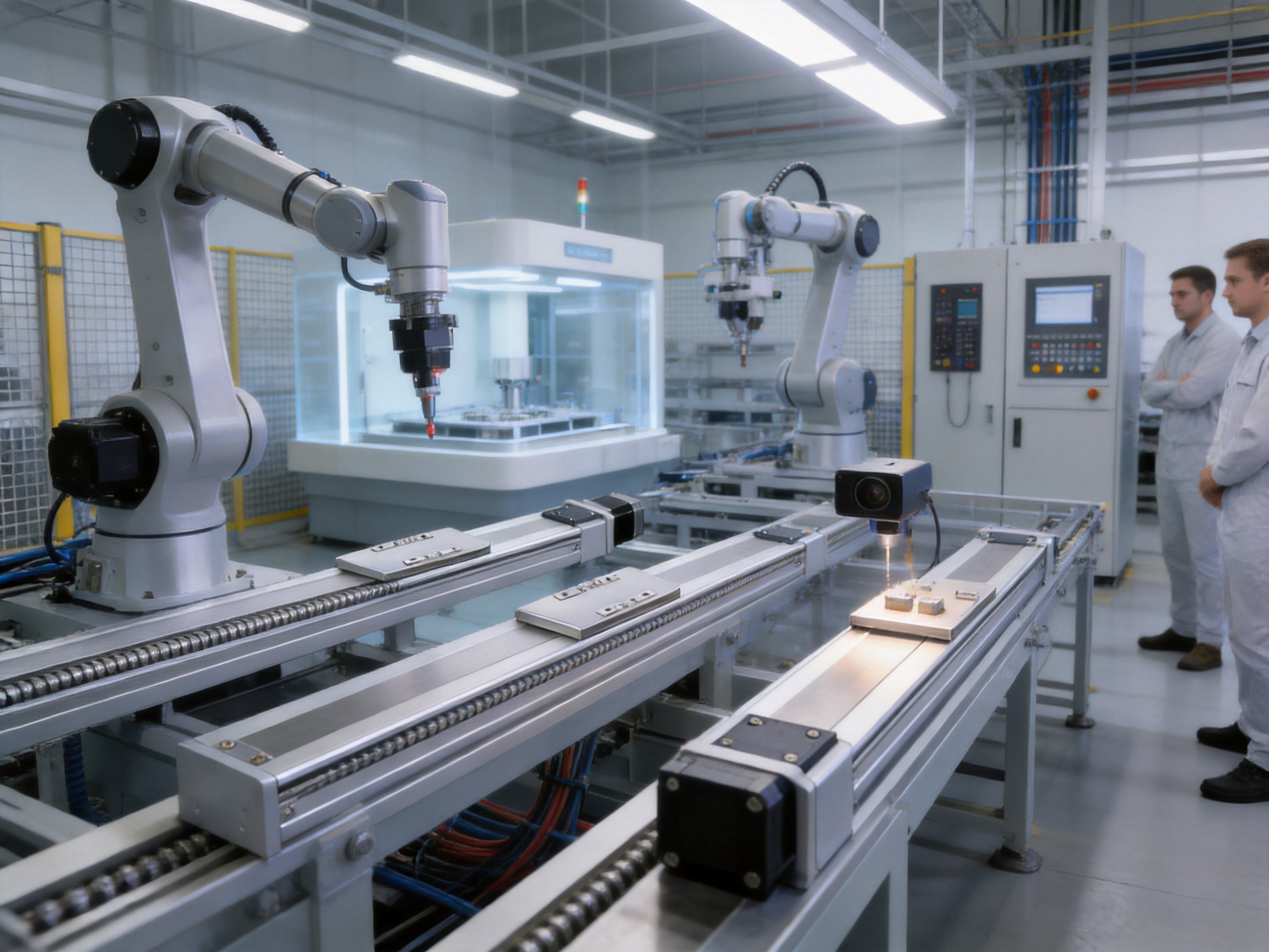
Precision automation increasingly depends on motion systems that can combine accuracy, speed, load capacity, compact installation, and dependable operation in one integrated assembly. The rail-embedded linear module described in this article is designed for that requirement. It uses a high-precision ball screw transmission, an integrated guide rail structure, a 100 W AC servo motor configuration, and multiple installation and motor-layout options. With repeatability specified at ±0.01 mm, the module is suitable for demanding positioning duties in precision machining, electronic component assembly, semiconductor equipment, inspection systems, laboratory automation, and intelligent manufacturing lines.
Unlike a basic belt-driven actuator or a conventional linear slide assembled from separate rails, carriages, brackets, and drive components, this product is engineered as a coordinated motion unit. The guide rail is embedded into the main body, the drive system is enclosed within the structural profile, and the motor can be configured on the right side, left side, bottom side, or in an exposed arrangement. This integrated approach reduces installation complexity while helping equipment designers achieve a cleaner layout and more predictable mechanical performance.
The module is manufactured and supplied by Suzhou Tongyousheng Electronic Technology Co., Ltd., a high-tech enterprise specializing in electric cylinders, linear motion modules, linear motor modules, servo presses, robotic seventh axes, and multi-degree-of-freedom motion platforms. The company combines product development, precision machining, electromechanical integration, application engineering, and customized automation support. Its capabilities allow the rail-embedded module to be used not only as an individual actuator but also as a building block in larger automated systems.
A rail-embedded linear module is a compact linear actuator in which the guide mechanism is incorporated into the body of the module rather than mounted as a completely separate external component. The slider travels along the integrated guide structure while the ball screw converts motor rotation into controlled linear motion. This design provides a stable path for the moving carriage and helps maintain alignment between the transmission system and the load-bearing elements.
The featured model is a ball screw driven rail-embedded linear module with a repeat positioning accuracy of ±0.01 mm. Its available stroke range extends from 50 mm to 800 mm in 50 mm increments. Depending on the selected ball screw lead, the maximum speed is 100 mm/s, 250 mm/s, or 500 mm/s. The same lead selections also influence thrust, payload, and motion responsiveness, allowing users to select a configuration according to whether their priority is force, speed, or a balance between the two.
The standard configuration uses a C7-grade ball screw with a 10 mm nominal diameter and a 100 W AC servo motor. A 7 × 8 mm coupling connects the motor to the transmission system. External home sensor options include EE-SX674(NPN) and FC-SPX307Z-2M(NPN). The module can be paired with servo motor and driver combinations from Mitsubishi, Panasonic, or Delta, subject to the selected motor arrangement and application requirements.
Its compact body is particularly valuable in equipment where installation space is restricted. By embedding the rail and transmission components into the actuator body, the module avoids the wider footprint often associated with separate guide rails and externally mounted drive systems. This can simplify machine design, reduce interference with adjacent components, and make it easier to create compact multi-axis mechanisms.
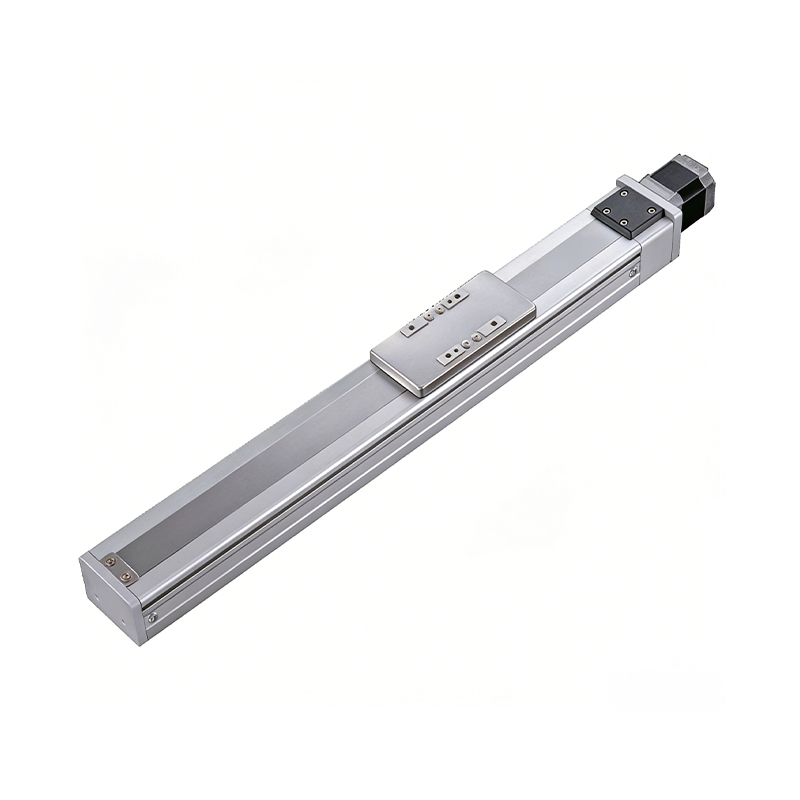
0.01mm High Precision Ball Screw Driven Rail-Embedded Linear Module
The principal performance advantage of this module is its specified repeatability of ±0.01 mm. Repeatability describes the ability of the actuator to return to the same position under consistent operating conditions. This characteristic is essential in applications such as component placement, optical inspection, precision dispensing, machining, probing, and assembly, where even a small positioning deviation can affect product quality.
The ball screw drive contributes to this result through its rolling-contact transmission. Compared with a simple sliding screw or a belt mechanism, a ball screw uses recirculating balls between the screw and nut. This reduces friction and allows rotary motion to be converted into linear movement with high efficiency. The result is smooth travel, lower mechanical resistance, and more consistent positioning when the system is correctly installed, lubricated, and operated within its rated conditions.
It is important to distinguish repeatability from absolute accuracy. Actual application accuracy can also be affected by servo tuning, thermal expansion, installation flatness, payload distribution, external vibration, screw alignment, and control resolution. Nevertheless, a repeatability specification of ±0.01 mm provides a strong foundation for precision automation and is considerably more suitable for demanding positioning tasks than many low-cost belt-driven modules.
The module is available with ball screw leads of 2 mm, 5 mm, and 10 mm. A smaller lead generally provides greater mechanical advantage and higher thrust, while a larger lead supports faster linear travel for the same motor speed. This range allows the actuator to be adapted to different operating priorities without requiring a completely different product platform.
| Ball Screw Lead | Maximum Speed | Maximum Horizontal Payload | Maximum Vertical Payload | Rated Thrust |
|---|---|---|---|---|
| 2 mm | 100 mm/s | 25 kg | 8 kg | 854 N |
| 5 mm | 250 mm/s | 20 kg | 8 kg | 285 N |
| 10 mm | 500 mm/s | 12 kg | 3.5 kg | 142 N |
The 2 mm lead is appropriate when high thrust, controlled low-speed motion, or heavier horizontal loads are the primary concerns. The 5 mm lead provides a practical compromise between speed and force for general automation. The 10 mm lead is better suited to applications where shorter cycle times and faster transfer are more important than maximum thrust.
These values should be evaluated together with acceleration, duty cycle, moment loading, overhang, installation direction, and the actual center of gravity of the payload. The published payload values are not universal limits for every operating condition. They represent rated conditions that should be confirmed against the machine layout and motion profile before final selection.
Stroke lengths from 50 mm to 800 mm are available at 50 mm intervals. This standardized range helps equipment designers select a travel length close to the real process requirement instead of using an unnecessarily long actuator. A properly selected stroke can reduce machine size, lower moving mass, and improve cycle efficiency.
Each stroke is associated with defined overall dimensions and mounting-hole positions. For the motor-right-side, motor-left-side, and motor-bottom-side arrangements, the body length is generally the selected stroke plus a fixed structural allowance. For example, the body length for the motor-right-side configuration is 246 mm at a 50 mm stroke and 996 mm at an 800 mm stroke. The exposed-motor arrangement adds additional length because of its motor configuration, with body lengths ranging from 264 mm to 1,014 mm across the same stroke range.
The 50 mm stroke version requires special installation attention. When the slider is positioned over the top mounting locations, some top mounting holes can be blocked. In that case, only four screws may be available for fixation through the top, and the manufacturer recommends using the bottom mounting holes to secure the body. This design note should be considered during machine layout and service planning.
A conventional linear motion assembly may require a separate guide rail, carriage, mounting plate, screw support, motor bracket, coupling cover, and alignment procedure. Every additional component introduces potential tolerance accumulation and increases the number of installation steps. The rail-embedded design reduces this complexity by integrating the guide rail into the actuator body.
This arrangement provides several practical benefits. First, it reduces the overall installation footprint. Second, it protects the guide mechanism and transmission components within a coordinated housing. Third, it makes the actuator easier to handle as a complete unit. Fourth, it helps reduce the number of interfaces that must be aligned during machine assembly. For equipment builders, these benefits can shorten integration time and lower the risk of assembly-related positioning errors.
Compared with a separately assembled rail and screw system, the integrated structure also allows the manufacturer to control the relationship between the drive axis and guide axis during production. This is important because parallelism, mounting flatness, and carriage alignment directly influence friction, noise, wear, and repeatability.
Belt-driven linear modules are often attractive because they can offer high speed and relatively low initial cost. However, belts can experience elastic deformation, tension variation, tooth wear, and vibration. These effects may become more noticeable during frequent reversing, high acceleration, or long-term operation. A belt drive may be suitable for lighter transfer tasks, but it is not always the preferred solution for precision positioning.
The ball screw transmission in this module is better suited to applications that require controlled positioning, higher thrust, and stable repeatability. Its rolling contact supports efficient power transmission, while the screw geometry provides a predictable relationship between motor rotation and linear displacement. The available lead options also allow users to balance speed and thrust more precisely than with a single standard belt ratio.
A ball screw module may not replace a belt actuator in every high-speed application. Belt systems can be advantageous for extremely long travel or very high-speed transport. However, for strokes up to 800 mm and positioning tasks requiring a compact, force-capable, and repeatable actuator, the ball screw architecture offers a compelling balance of performance.
Space is often one of the most expensive resources in modern automation equipment. A separate rail assembly may require additional width, side clearances, support plates, and protective covers. The rail-embedded module reduces the amount of external hardware needed around the motion axis. This makes it easier to arrange several axes close together or install the actuator within a compact machine frame.
The compact body is particularly beneficial in electronic assembly equipment, inspection stations, laboratory instruments, and robotic mechanisms where components must be positioned around a limited working envelope. The different motor-side options further improve layout flexibility. A design engineer can select right-side, left-side, bottom-side, or exposed motor placement according to cable routing, neighboring axes, maintenance access, and available clearance.
The module is designed to maintain stable positioning performance during long-term continuous operation when used within catalog specifications. The manufacturer states a guaranteed service life of 10,000 km under normal operating conditions and with appropriate compliance with the specified requirements. Service life is influenced by payload, speed, acceleration, lubrication, environment, installation quality, and moment loading, so the value should be interpreted as a rated design reference rather than a guarantee for every application.
Compared with a lightly constructed actuator intended only for intermittent movement, the integrated ball screw and guide arrangement is more appropriate for repetitive industrial duty. The enclosed structure helps organize and protect the motion components, while the servo motor provides closed-loop control potential and precise velocity and position management.
Payload capacity depends on ball screw lead and installation direction. In horizontal operation, the maximum listed payload ranges from 12 kg to 25 kg. The 2 mm lead provides the highest horizontal payload at 25 kg, the 5 mm lead supports up to 20 kg, and the 10 mm lead supports up to 12 kg.
Vertical installation creates more demanding conditions because the actuator must support the load against gravity. The listed vertical payload is 8 kg for the 2 mm and 5 mm leads and 3.5 kg for the 10 mm lead. A vertical application may also require a brake-equipped servo motor to prevent unintended downward movement when power is removed. The available motor options include brake and no-brake variants for several major servo brands.
Payload calculations should include the end tooling, brackets, cables, workpiece, and any moving fixtures. Engineers should also consider acceleration forces. A payload that is acceptable during slow movement may exceed the allowable dynamic load during rapid acceleration or deceleration.
The actuator is subject not only to direct payload but also to bending moments created when the center of gravity is offset from the slider. The allowable overhang data provides guidance for horizontal, wall-mounted, and vertical installation. For example, under particular horizontal conditions, a 12 kg load may be associated with an allowable dimension of approximately 1,000 mm in the published table, while heavier loads reduce the allowable distance. In wall-mounted installation, the permitted values differ because the direction of the load and moment changes.
For vertical installation, the table provides separate values for lower payload classes. Depending on the lead and load, allowable dimensions such as 195 mm, 150 mm, 100 mm, or 75 mm are shown. These values demonstrate why load placement is as important as load mass. A relatively light payload can still create a significant moment if mounted far from the center of the slider.
When designing an end-effector, it is advisable to keep the center of gravity close to the actuator’s supported area. If a long arm or offset tooling arrangement is unavoidable, the designer should calculate the resulting moments and verify them against the module’s allowable limits. Additional support, a larger actuator, or a different axis arrangement may be required.
| Moment Type | Permitted Value |
|---|---|
| MY | 79 N·m |
| MP | 79 N·m |
| MR | 116 N·m |
The published static loading moments are MY 79 N·m, MP 79 N·m, and MR 116 N·m. These values represent loading about the relevant axes and are based on the center-of-gravity reference used in the product documentation. They should be checked against actual tooling geometry, acceleration, shock, and dynamic duty cycle.
Moment ratings are especially relevant in pick-and-place systems, inspection arms, dispensing heads, screwdriving tools, and robotic end-effectors. By reviewing the load center during the initial design stage, users can avoid excessive friction, premature wear, uneven guide loading, and positioning errors.
The standard product configuration is designed around a 100 W AC servo motor. Servo control is beneficial where the application requires controlled acceleration, repeatable positioning, rapid reversals, fault monitoring, and integration with a programmable motion controller. A servo system can also provide feedback for detecting following errors, overload conditions, and unexpected mechanical resistance.
| Brand | Brake Option | Motor Model | Driver Model | Rated Power | Voltage |
|---|---|---|---|---|---|
| Mitsubishi | Without brake | HG-KN13J-S100 | MR-JE-10A | 100 W | 220 V |
| Mitsubishi | With brake | HG-KN13BJ-S100 | MR-JE-10A | 100 W | 220 V |
| Panasonic | Without brake | MSMF012L1U2M | MADLN05SE | 100 W | 220 V |
| Panasonic | With brake | MSMF012L1V2M | MADLN05SE | 100 W | 220 V |
| Delta | Without brake | ECM-B3L-C20401RS1 | ASD-B3-0121-L | 100 W | 220 V |
| Delta | With brake | ECM-B3L-C20401SS1 | ASD-B3-0121-L | 100 W | 220 V |
For horizontal applications, a no-brake motor may be appropriate when the load cannot move significantly under its own weight after power removal. For vertical applications, a brake-equipped motor is commonly preferred because it can help hold the axis when the servo is disabled. The final selection should be based on the machine risk assessment, load characteristics, stopping requirements, and controller architecture.
Compatibility with multiple established servo brands gives system integrators greater flexibility. Many factories standardize on a preferred control platform, and the ability to select Mitsubishi, Panasonic, or Delta equipment can simplify spare-parts management and maintenance training. It can also make the module easier to integrate into existing production lines.
External home sensor options include the EE-SX674(NPN) and FC-SPX307Z-2M(NPN). A home sensor establishes a repeatable reference position during machine startup or recovery. This is important in systems where the controller must know the axis location before executing automatic movement.
Homing can be used together with servo encoder feedback and software travel limits. The sensor provides a physical reference, while the controller can define working coordinates, motion limits, approach speeds, and offset positions. Proper sensor placement and shielding are important in environments containing electrical noise, vibration, coolant, dust, or reflective surfaces.
A well-designed homing routine normally approaches the sensor at a controlled speed, detects the reference signal, reverses or reduces speed as needed, and establishes a repeatable zero position. The exact procedure depends on the servo drive and motion controller. Engineers should verify sensor logic, wiring, response time, and fail-safe behavior during commissioning.
The motor-right-side and motor-left-side configurations provide similar primary dimensional data while allowing the motor and cable direction to be placed on the preferred side of the machine. This can simplify axis stacking and prevent interference between adjacent actuators. In a two-axis or three-axis system, opposing motor locations may create a more compact arrangement and improve access to connectors.
These configurations are suitable for horizontal transfer mechanisms, inspection stages, dispensing units, loading systems, and assembly equipment. The main body remains compact while the motor position can be adapted to the machine frame. During design, users should reserve sufficient clearance for motor housing, cables, connectors, maintenance tools, and possible replacement of the coupling or sensor.
The motor-bottom-side configuration is valuable when side clearance is limited or when the top and sides of the module must remain unobstructed. It can be used in stacked systems, vertical frames, or machinery where the motor needs to be positioned beneath the structural support. This arrangement may also help reduce interference with workpieces or tooling above the slide.
Bottom-side motor mounting should be evaluated together with service access and cable routing. The supporting frame must be sufficiently rigid to prevent deformation, and the motor should not be exposed to excessive heat, liquid, debris, or impact from below. As with every configuration, the actuator should be mounted on a sufficiently flat and stable reference surface.
The exposed-motor configuration provides a different layout option where the motor extends outside the main body. It may be useful when the application requires a specific motor orientation or when the standard side and bottom arrangements do not provide enough clearance. Because the exposed arrangement has a greater overall length, the machine designer must account for the additional motor envelope during layout.
Exposed components should be protected where the machine environment includes dust, oil mist, chips, moisture, or accidental contact. Appropriate guards and cable supports may be required. This configuration can still offer practical benefits when accessibility, replacement, or a particular axis geometry is more important than the most compact overall length.
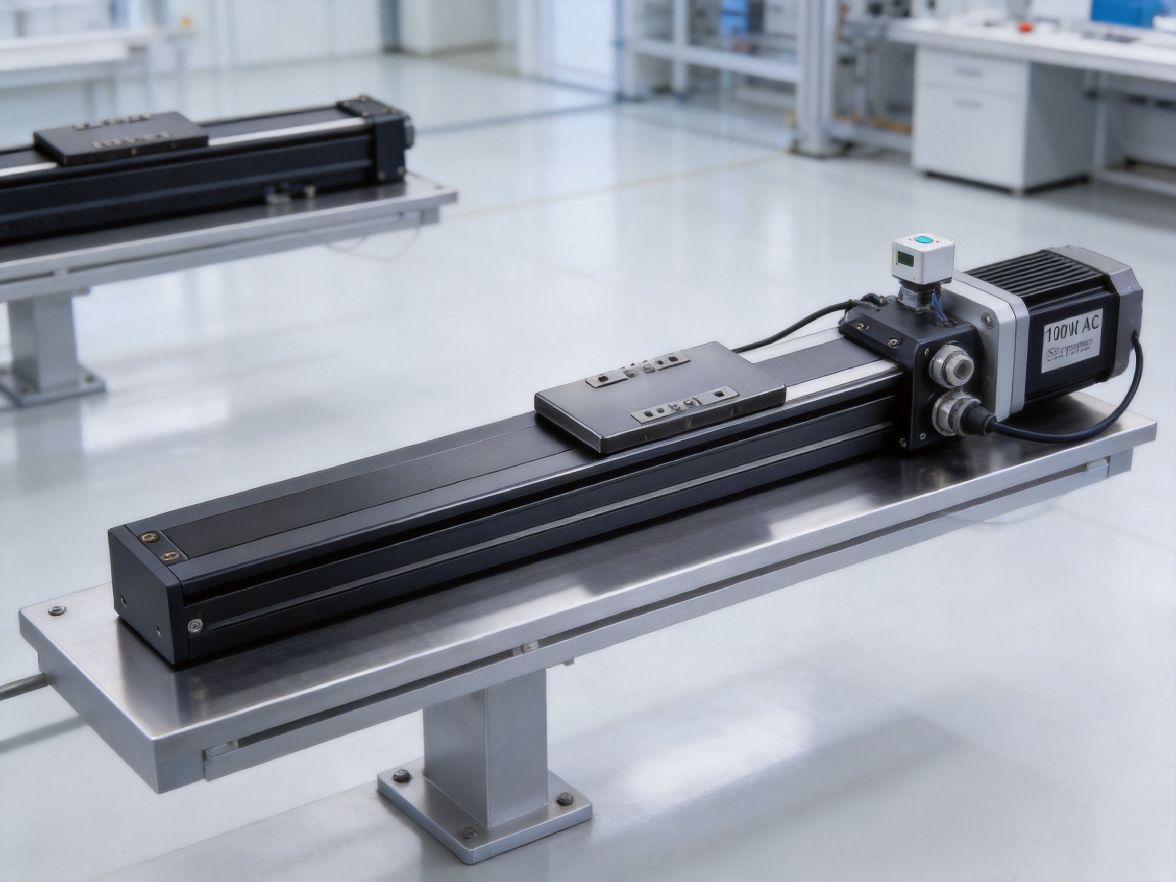
The performance of a precision linear module depends on more than the selected screw and motor. It also depends on the accuracy of the body, the quality of machining, the consistency of assembly, the inspection process, and the engineering discipline used to match components. Suzhou Tongyousheng Electronic Technology Co., Ltd. combines research and development, production, and sales in one organization, supporting closer coordination between design and manufacturing.
The company maintains an experienced research and development team focused on automation equipment and motion components. Its product portfolio includes electric cylinders, linear motion modules, linear motor modules, servo presses, robotic seventh axes, six-degree-of-freedom platforms, control software, and multi-degree-of-freedom linkage systems.
This broad product range is valuable because motion applications often require more than one actuator. A linear module may be used as part of a multi-axis gantry, a robotic extension axis, a servo press feeder, or a motion simulation platform. Experience across several product categories helps engineers understand load transfer, synchronization, control integration, mechanical stiffness, and system-level reliability.
The company’s development process uses advanced design software and mechanical engineering methods to evaluate structural strength, component relationships, installation interfaces, and movement envelopes before production. This supports the creation of standardized product platforms while leaving room for customized motor arrangements, stroke lengths, sensors, and application-specific integration.
High-precision CNC machining centers are used to manufacture the structural elements of the module. CNC machining allows the body, mounting surfaces, holes, and critical interfaces to be produced according to controlled digital designs. Consistent machining is essential for maintaining rail alignment, screw positioning, mounting repeatability, and overall structural rigidity.
Machining quality directly affects how smoothly the slider travels. If mounting surfaces are uneven, or if the guide and screw axes are not correctly related, the mechanism may experience increased friction, vibration, or uneven loading. A controlled machining process helps reduce these risks and provides a more reliable basis for final assembly.
Precision machining also makes it easier to maintain dimensional consistency across different stroke lengths. The product range includes many standardized travel options, so repeatable production methods are important for ensuring that each length variant maintains the intended mounting-hole pattern and mechanical relationship.
The module is not simply a machined rail. It is an integrated electromechanical product that combines the structural body, guide system, ball screw, coupling, servo motor, sensor, and control compatibility. The manufacturer’s experience with electric cylinders and servo presses supports the integration of motor-driven mechanisms with industrial control systems.
Integration reduces the burden on customers. Instead of sourcing each mechanical and electrical component separately, the user can select a pre-engineered configuration and focus on machine-level programming, tooling, and process optimization. This can shorten procurement cycles and reduce the possibility of incompatibility between the motor, screw, coupling, sensor, and mounting structure.
The company also supports customized automation solutions. Where a standard stroke, motor arrangement, or sensor layout does not meet the application, the engineering team can review the requirements and propose a suitable configuration. Customization should be confirmed through technical consultation, particularly when the application involves unusual loads, high duty cycles, cleanroom requirements, special environmental protection, or nonstandard installation orientations.
The company maintains a portfolio of core patents and places technological innovation at the center of its development strategy. Patent activity in automation can cover mechanical structures, transmission arrangements, control methods, synchronized motion, platform mechanisms, and specialized equipment designs. Such development work supports differentiation from commodity actuators that compete only on basic price and standard dimensions.
Its collaboration with state-owned enterprises, defense technology institutions, and leading universities also contributes to the development of advanced motion technologies. These collaborations help connect practical manufacturing requirements with research in mechanical design, control algorithms, motion simulation, and intelligent manufacturing.
In precision machining equipment, the module can be used for tool positioning, workpiece transfer, probing, fixture adjustment, or auxiliary axis movement. Its ball screw drive provides the force and positioning control needed for repetitive mechanical operations. The appropriate lead should be selected according to cutting forces, travel speed, payload, and required resolution.
Electronic assembly lines often require compact axes that can position feeders, inspection cameras, grippers, dispensing heads, or soldering tools. The integrated rail design helps preserve valuable machine space, while the ±0.01 mm repeatability supports repeatable placement and inspection operations. The motor and sensor options can be matched with the factory’s existing control architecture.
Semiconductor-related equipment places strong emphasis on repeatability, smooth movement, low vibration, compactness, and process stability. The module can be considered for wafer handling subassemblies, inspection stages, alignment mechanisms, and auxiliary positioning axes, provided that the environmental and cleanliness requirements are verified. Standard catalog construction may require additional protection or special preparation for demanding cleanroom or controlled-environment applications.
Inspection systems require accurate movement of cameras, probes, sensors, or workpieces. The actuator can provide controlled linear travel for scanning, focusing, calibration, and part positioning. A servo drive allows the motion profile to be adjusted for different inspection routines, while the home sensor establishes a repeatable reference after startup.
Robotic seventh axes extend the working range of industrial robots by moving the robot along a linear track. The rail-embedded module may serve as a compact auxiliary axis for smaller robot systems or tooling movements. For larger robots or long travel, the load and moment calculations must be performed carefully, and a larger platform may be more appropriate.
Servo presses and automated feeding equipment often require synchronized positioning, controlled acceleration, and repeatable transfer. The module can be used for feeder adjustment, part loading, fixture positioning, and pre-press or post-press handling. The manufacturer’s experience with servo presses allows the motion component to be considered as part of a broader production solution rather than as an isolated actuator.
Laboratory instruments benefit from compact, controllable motion modules for sample handling, scanning, dosing, positioning, and test automation. The available stroke options and motor layouts make it possible to build small mechanisms without excessive structural bulk. In research systems, the flexibility to select different leads can help balance speed during setup with precision during measurement.
The first step in selecting the module is to define the required stroke. The selected travel should be long enough to cover the working range while avoiding unnecessary excess. A longer actuator generally increases body length and moving mass, so a close match between required travel and catalog stroke can improve machine efficiency.
The second step is to determine the installation direction. Horizontal, wall-mounted, and vertical installations impose different loads on the guide and screw. Vertical applications require particular attention to brake selection, gravitational load, emergency stopping, and safe power-off behavior.
The third step is to calculate the payload and center of gravity. Include the workpiece, tooling, brackets, cables, sensors, and any moving fixtures. Then determine the resulting forces and moments during acceleration and deceleration. The static MY, MP, and MR values should be used as reference limits, and dynamic effects should not be ignored.
The fourth step is to select the ball screw lead. Choose the 2 mm lead when force and load capacity are priorities, the 5 mm lead for a balanced general-purpose solution, and the 10 mm lead when faster travel is more important. Confirm that the chosen lead provides sufficient speed at the available motor speed and sufficient thrust for the required acceleration.
The fifth step is to select the motor arrangement. Right-side, left-side, bottom-side, and exposed configurations should be compared using the complete machine envelope. Cable routing, connector access, maintenance clearance, heat dissipation, and interference with adjacent mechanisms should all be reviewed.
The sixth step is to select the motor and driver. The listed Mitsubishi, Panasonic, and Delta combinations provide common industrial alternatives. A brake-equipped motor is generally preferred for vertical axes, while a no-brake motor may be suitable for many horizontal applications. Final selection should be confirmed with the motion controller and safety system.
The final step is to validate the operating environment. Temperature, humidity, dust, oil mist, chips, vibration, washdown, cleanroom requirements, and corrosive substances can influence the appropriate configuration. If the application exceeds standard conditions, the manufacturer should be consulted before ordering.
The mounting surface should be sufficiently flat, rigid, and clean. Uneven support can distort the body and increase guide loading. Mounting screws should be tightened according to an appropriate sequence so that the actuator remains correctly seated. The machine frame should be checked for deflection under the expected payload and acceleration.
During commissioning, move the slider at low speed and verify travel limits, sensor signals, motor direction, encoder feedback, and emergency stop behavior. Confirm that the home sensor is detected consistently and that the controller establishes the correct coordinate offset. Check for abnormal noise, vibration, heating, or resistance before operating at full speed.
Lubrication should follow the manufacturer’s recommendations and the actual operating environment. Excessive contamination can shorten the service life of the ball screw and guide mechanism. Periodic inspection should include mounting bolts, coupling condition, cables, sensor brackets, unusual wear, and changes in positioning behavior.
Long-term service life depends on using the module within its rated payload, speed, moment, and installation conditions. The published 10,000 km service-life reference assumes normal use and compliance with the product specifications. Applications involving shock loads, rapid cycling, high contamination, or substantial overhang may require a more conservative maintenance schedule.
The product combines several qualities that are often purchased separately: compact construction, integrated guidance, ball screw transmission, servo compatibility, flexible stroke selection, and repeatable positioning. Its ±0.01 mm repeatability makes it more suitable for precision work than many basic transfer actuators, while its available payload and thrust options allow it to handle more demanding tasks than lightweight positioning slides.
The rail-embedded structure offers a practical advantage over assemblies that rely on separate external rails. It reduces component count, saves installation space, and can make system integration more straightforward. Multiple motor mounting options provide additional freedom when designing compact equipment or multi-axis mechanisms.
The manufacturer adds value through its broader engineering background. Its experience covers electric cylinders, linear modules, servo presses, linear motor systems, robotic axes, motion simulation platforms, and intelligent manufacturing equipment. This enables customers to obtain not only a standard actuator but also technical support for more complex automation projects.
Advanced design software, high-precision CNC machining centers, an experienced R&D team, and core technical patents support the company’s ability to develop and manufacture precision motion products. Its cooperation with industrial organizations and universities further strengthens its ability to address specialized requirements and emerging automation applications.
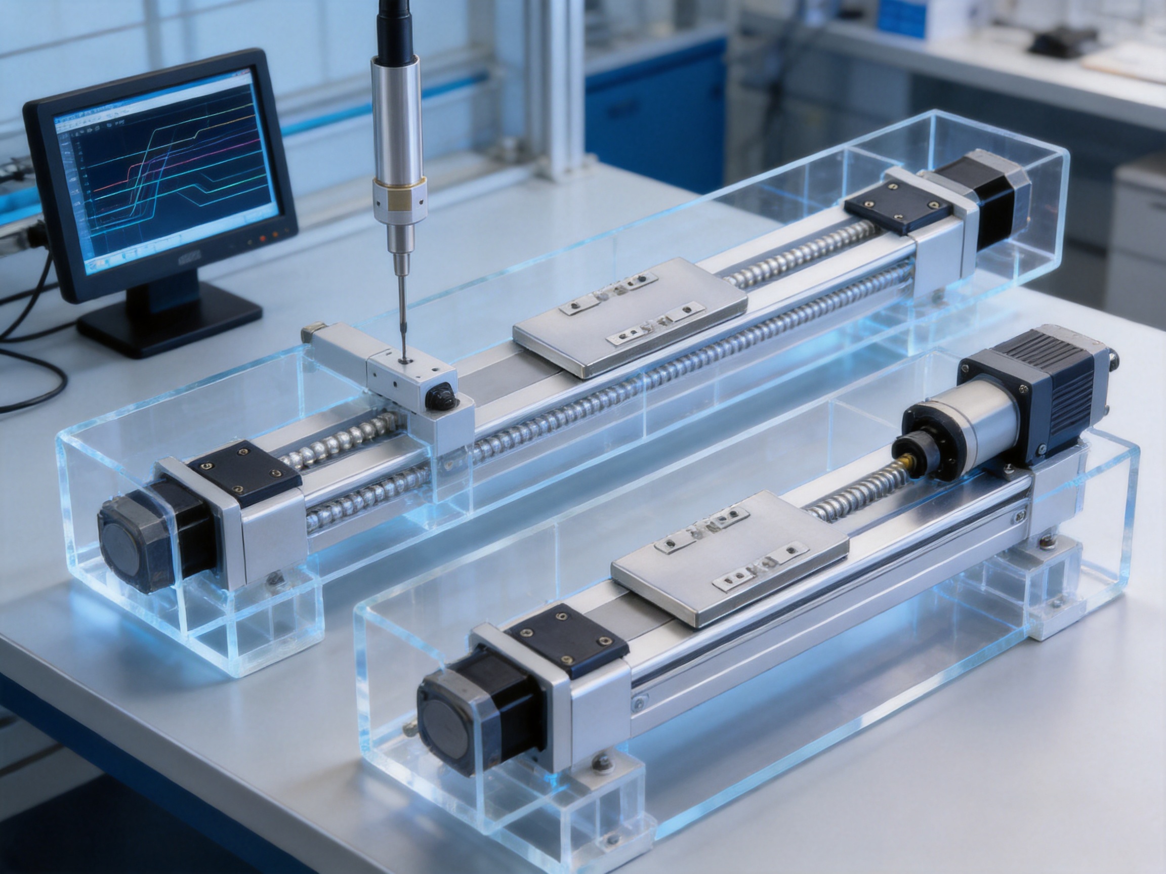
The specified repeat positioning accuracy is ±0.01 mm. Actual performance depends on servo tuning, installation, temperature, payload, acceleration, lubrication, and operating conditions.
Available strokes range from 50 mm to 800 mm in 50 mm increments. The appropriate length should be selected according to the required working travel and machine envelope.
The available leads are 2 mm, 5 mm, and 10 mm. The 2 mm lead offers the highest listed thrust, while the 10 mm lead offers the highest listed speed. The 5 mm lead provides an intermediate configuration.
The maximum listed speed is 100 mm/s with the 2 mm lead, 250 mm/s with the 5 mm lead, and 500 mm/s with the 10 mm lead.
Yes, it can be used in vertical applications within the stated payload, speed, moment, and installation limits. A brake-equipped servo motor is generally recommended for vertical axes to help hold the load when power is removed.
The documented options include 100 W Mitsubishi, Panasonic, and Delta AC servo motors and corresponding drivers. Both brake and no-brake versions are available for several configurations.
External home sensor options include EE-SX674(NPN) and FC-SX307Z-2M(NPN) as specified in the product information. Wiring and controller compatibility should be verified before installation.
The listed values are MY 79 N·m, MP 79 N·m, and MR 116 N·m. These values must be compared with the actual center of gravity, tooling dimensions, and dynamic loads.
Yes. The product structure supports motor-right-side, motor-left-side, motor-bottom-side, and motor-exposed arrangements. The selected arrangement should match the machine’s clearance, cable, and maintenance requirements.
It is designed for stable performance during long-term operation when used within the catalog specifications. The stated guaranteed service life is 10,000 km under normal compliant use. Actual service life depends on the application environment and operating profile.
The manufacturer provides automation solutions and can review customized requirements involving motor selection, stroke, sensors, installation, and system integration. Special environmental or loading conditions should be discussed before ordering.
The standard specification does not apply to ceiling-mounted inverted use. Users requiring this arrangement should contact the manufacturer for technical confirmation and an appropriate design review.
The 0.01 mm high-precision ball screw driven rail-embedded linear module is a compact and versatile solution for industrial automation requiring repeatable positioning, controlled motion, and efficient use of installation space. Its integrated rail structure reduces the complexity of traditional linear assemblies, while its ball screw drive provides a strong combination of thrust, smooth movement, and positioning stability.
With stroke options from 50 mm to 800 mm, three ball screw leads, multiple motor orientations, external home sensor choices, and compatibility with widely used servo brands, the module can be adapted to a broad range of machine designs. Its performance is particularly relevant to precision machining, electronics assembly, semiconductor equipment, inspection, robotic axes, servo press systems, and laboratory automation.
The product is also supported by a manufacturer with capabilities extending from research and development to precision CNC machining, electromechanical integration, servo systems, and complete automation equipment. This combination of product engineering and manufacturing strength makes the module a practical choice for both standard machine construction and customized intelligent manufacturing projects.
For successful deployment, users should evaluate stroke, lead, payload, installation direction, center of gravity, static moments, acceleration, braking, environmental conditions, and maintenance requirements as one complete system. When those factors are properly matched, the rail-embedded linear module can provide a reliable foundation for compact, accurate, and efficient motion automation.
1. Product technical specifications for the high-precision ball screw driven rail-embedded linear module.
2. Product dimensional and installation data for motor-right-side, motor-left-side, motor-bottom-side, and motor-exposed configurations.
3. Ball screw transmission principles and industrial linear motion design practices.
4. Servo motor and driver selection information for Mitsubishi, Panasonic, and Delta 100 W AC servo systems.
5. General guidelines for payload, overhang, static moment, homing, lubrication, and service-life evaluation in linear actuator applications.
6. Corporate technical information regarding automation equipment, precision machining, research and development, and intelligent manufacturing solutions.
0.01mm High Precision Ball Screw Driven Rail-Embedded Linear Module
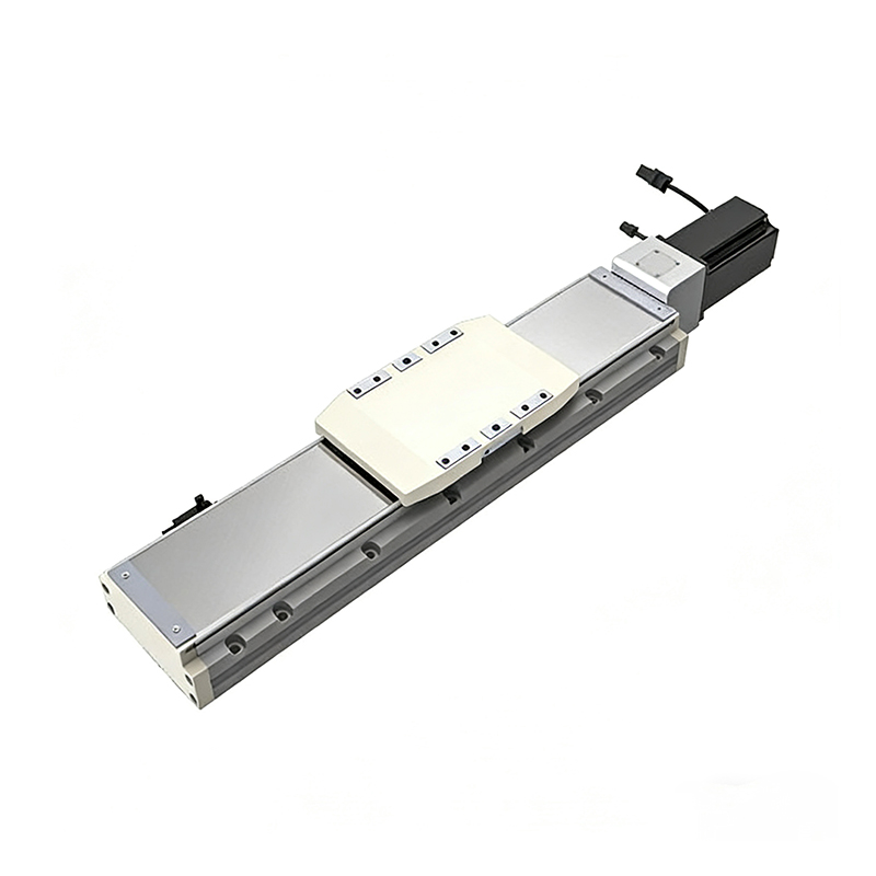 Heavy Load Ball Screw Driven Rail-Embedded Linear Module
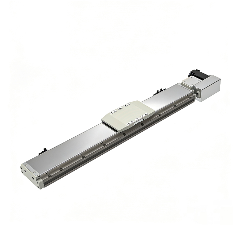 110KG Load Long Stroke Rail-Embedded Linear Module
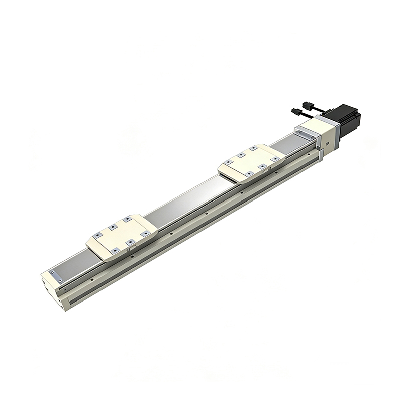 Dual-Slider High Precision Rail-Embedded Linear Module
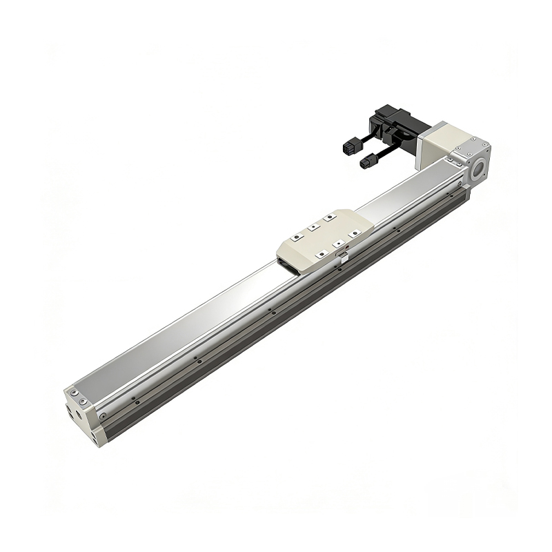 Belt Driven Dust-Proof Rail-Embedded Linear Module
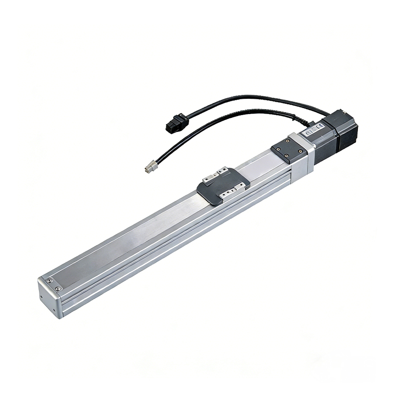 0.01mm High Precision Light Load Ball Screw Linear Module
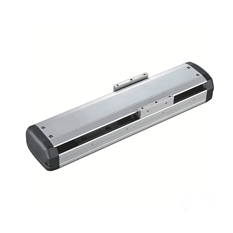 Ball Screw Linear Module with Built-in Sensor
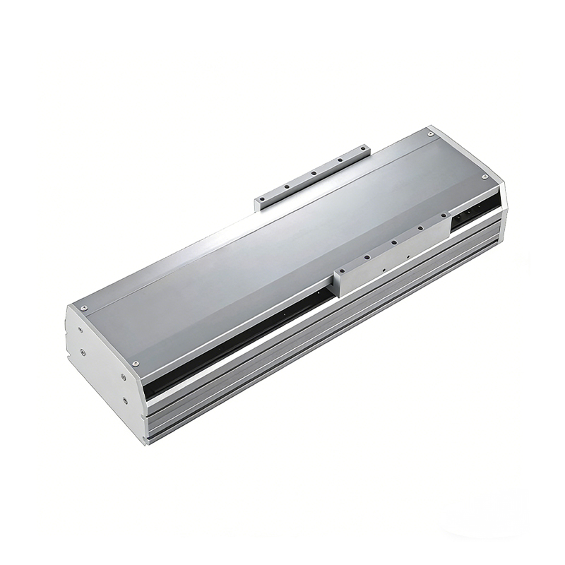 2000mm Long Stroke Ball Screw Linear Module
This 2000mm Long Stroke Ball Screw Linear Module is customized for large-range linear movement automation tasks, support...
READ MOREThis 2000mm Long Stroke Ball Screw Linear Module is customized for large-range linear movement automation tasks, support...
READ MOREThis 2000mm Long Stroke Ball Screw Linear Module is customized for large-range linear movement automation tasks, support...
READ MOREThis 2000mm Long Stroke Ball Screw Linear Module is customized for large-range linear movement automation tasks, support...
READ MORE
If you are interested in our products, please leave us a message. We look forward to providing you with
professional services!
Innovation and transcendence make factory intelligent manufacturing efficient and convenient!
+86 186 2508 0683
19962977901
sales@sz-tys.com
Building 5, Suzhou Mudu International Science and Technology Innovation Park, Jinfeng South Road, Suzhou City, Jiangsu Province, China
