


 English
 Français
 русский
 عربى
عربى Español
 Deutsch
Tel
+86 186 2508 0683

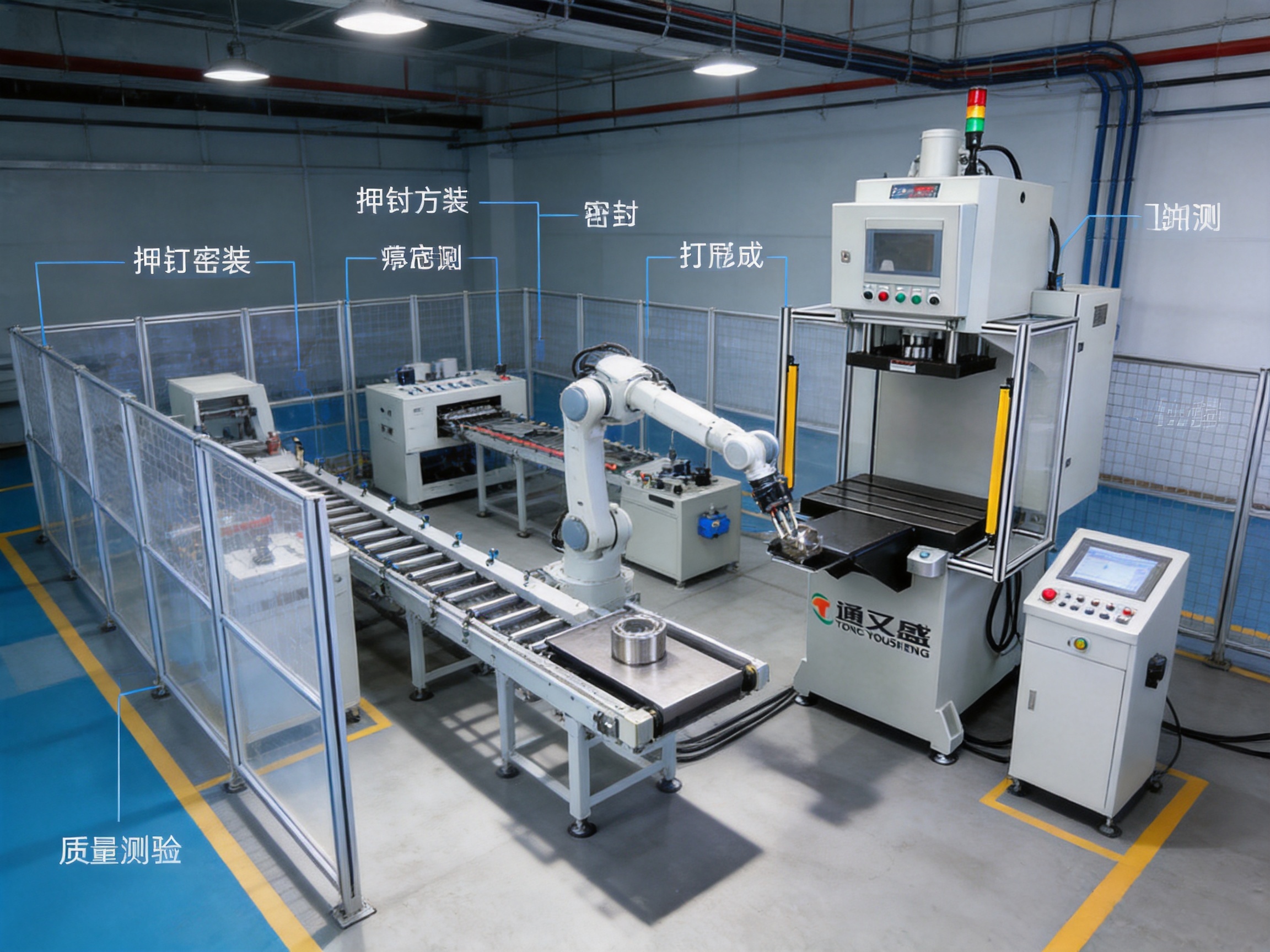
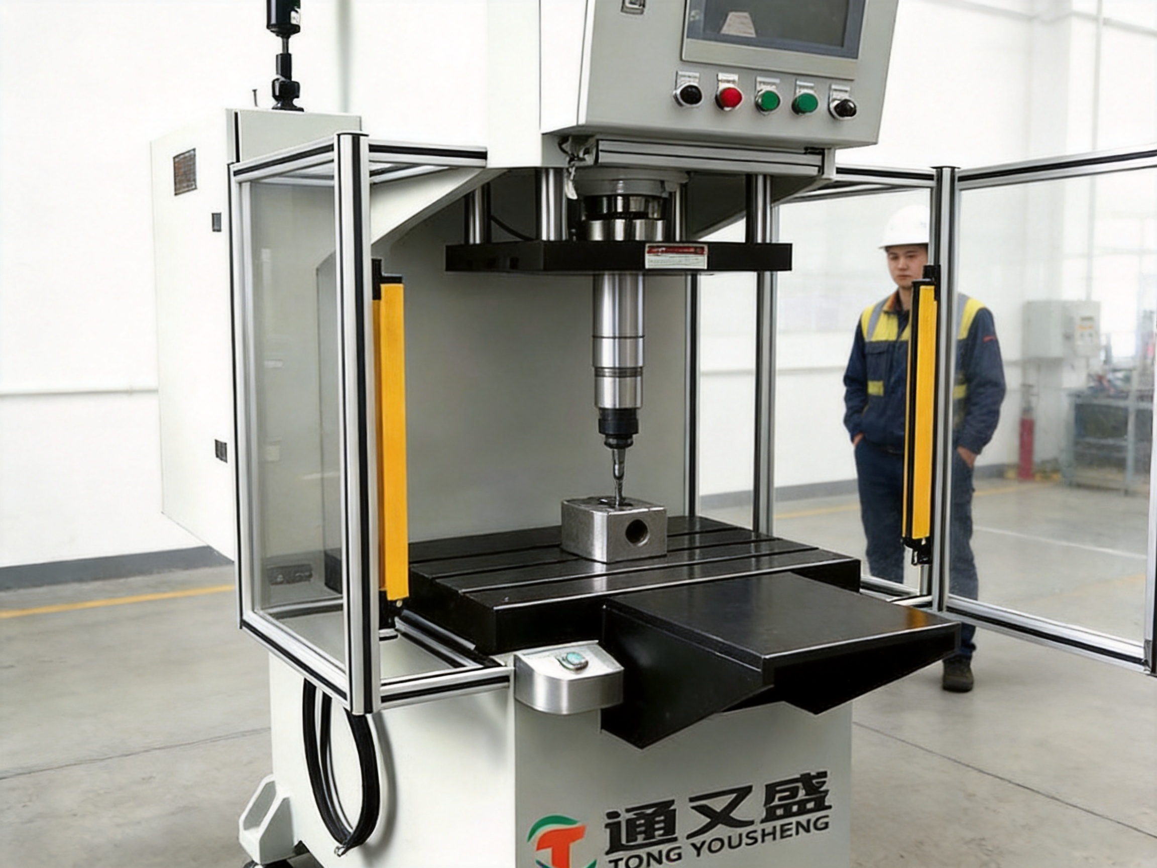
The C-frame single-column CNC servo hydraulic press machine is designed for manufacturers that need controlled force, accurate movement, repeatable pressing, and flexible integration into modern production systems. Its open C-type construction, sliding worktable, programmable hydraulic control, and comprehensive safety configuration make it suitable for press-fit assembly, stamping, forming, riveting, sealing, powder compacting, spring testing, and other force-displacement applications.
Unlike conventional hydraulic presses that often rely on manually adjusted valves and fixed operating sequences, this CNC servo hydraulic press combines programmable pressure, stroke, speed, dwell time, and stopping position. The result is a machine that can adapt to different products and process requirements while recording important production data for quality analysis and traceability.
The equipment is available in multiple capacity configurations, from compact 1 kN systems to larger 300 kN models. This range enables manufacturers to select a press that matches the required working force, stroke, speed, workpiece dimensions, and production rhythm without unnecessarily oversizing the machine.
Manufactured by Suzhou Tongyousheng Electronic Technology Co., Ltd., the press reflects the company’s broader expertise in electric cylinders, linear motion modules, linear motor modules, servo pressing systems, robotic motion solutions, and multi-degree-of-freedom platforms. The company combines mechanical design, precision machining, control development, assembly, testing, and application engineering to provide complete automation equipment rather than isolated machine components.
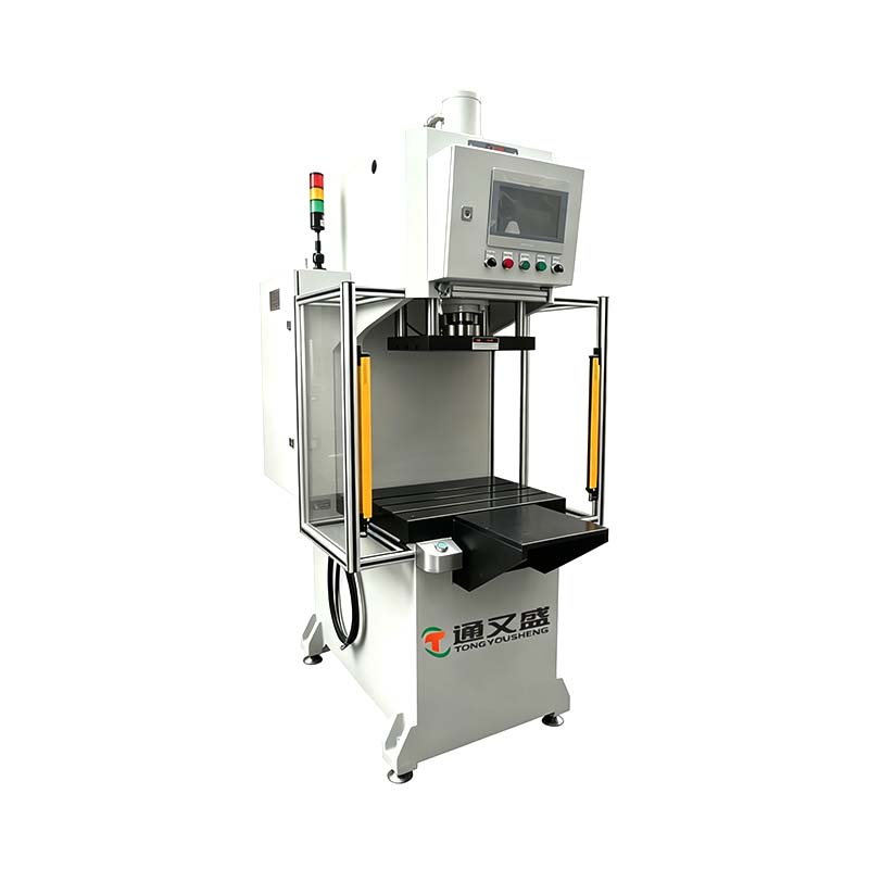
C Frame Single Column CNC Servo Hydraulic Press Machine
A C-frame single-column CNC servo hydraulic press is a compact forming and assembly machine built around an open-sided frame. The “C-frame” configuration creates clear access to the working area from the front and sides, making it easier for an operator or automated handling system to load and unload workpieces.
The single-column structure provides a practical balance between accessibility, rigidity, and equipment footprint. It is particularly useful when the workpiece is large, irregularly shaped, or difficult to position through a closed-frame press. A sliding worktable further improves access by allowing the tooling or workpiece to move outward from the pressing zone during loading, unloading, inspection, and tool change operations.
The press uses a hydraulic actuator to generate force. A CNC control system coordinates the actuator movement and monitors the process. Depending on the selected program, the machine can control press-fit position, pressing force, movement speed, holding time, return movement, and stopping position. The system can also monitor the relationship between force and displacement, which is essential for verifying whether an assembly or forming operation has been completed correctly.
In a typical press-fit cycle, the machine moves rapidly toward the workpiece, changes to a controlled pressing speed, applies the required force, maintains that force or position for a programmed dwell period, and then returns to its initial position. Every step can be configured according to the product and tooling requirements.
The open C-frame structure is one of the machine’s most important advantages. Operators can approach the tooling from several directions, reducing the handling difficulty associated with bulky or long workpieces. This is valuable in automotive, hardware, electrical, appliance, and general industrial production.
Compared with enclosed four-column or box-frame equipment, a C-frame press generally offers easier visual access to the work area. Operators can inspect tooling alignment, confirm workpiece placement, and monitor the pressing operation without working through a narrow opening. When integrated with robots or linear transfer systems, the open structure also provides a convenient path for automatic loading and unloading.
The frame is engineered to support the applied load while maintaining the alignment required for repeatable pressing. Proper structural design is important because frame deflection can influence force distribution, tooling life, dimensional accuracy, and product quality. Tongyousheng’s manufacturing approach combines mechanical calculation, three-dimensional design, precision fabrication, and dimensional inspection to support consistent machine performance.
The sliding worktable allows the tooling area to move toward the operator. This design simplifies the placement of large, heavy, or awkward workpieces and reduces the need to reach deep into the machine. It can also shorten loading and unloading time, supporting a more efficient production cycle.
A sliding table is especially useful for operations that require frequent tooling changes or manual positioning. Tooling can be accessed more directly, and operators can perform visual checks outside the main pressing zone. In automated production, the table can be coordinated with material handling equipment, sensors, and robotic systems.
The table arrangement also supports flexible production. A manufacturer may use interchangeable fixtures for several components, provided that the tooling dimensions and pressing force remain within the selected machine’s limits. This flexibility helps reduce the need for separate dedicated machines for every product variation.
The CNC hydraulic system enables users to program key operating parameters instead of relying only on manual adjustment. Pressure, stroke, speed, dwell time, and stopping position can be configured according to the process recipe. Different products can therefore use different parameters while sharing the same press platform.
Programmable control improves repeatability because the machine follows defined values for each cycle. It also reduces dependence on operator experience. A trained operator remains important for setup and inspection, but the production sequence itself can be standardized and protected against unintentional changes.
The control system can be configured to monitor process conditions such as force and displacement. This enables the machine to identify abnormal pressing curves, insufficient insertion depth, excessive resistance, incorrect workpiece placement, or other process deviations. Depending on the production system, the result can be displayed on the HMI, recorded for later analysis, or transmitted to a factory data system.
Force-displacement monitoring is essential for high-quality assembly and forming. A force value alone may not reveal whether a component has reached the correct position. Likewise, a position value alone may not show whether the required resistance or interference fit has been achieved.
By monitoring both parameters, the machine can evaluate the complete pressing process. For example, a correct press-fit operation may require a specified force range at a particular insertion depth. If the force is too low, the component may be loose or missing. If the force is too high, the part may be misaligned, damaged, or dimensionally incorrect. If the final position is not reached, the assembly may be incomplete.
The press is suitable for applications in which the relationship between force and movement must be controlled or documented. These include bearing insertion, bushing assembly, connector insertion, riveting, forming, spring testing, and controlled stamping.
The machine can be used across many industrial processes. Its principal application categories include press-fit assembly, punching, riveting, powder compacting, sealing, spring testing, stamping, and forming.
In press-fit assembly, the equipment controls insertion force, travel, speed, and final position. In punching, it provides controlled movement and force for producing holes or forming features. In riveting, it can help maintain consistent force and stroke to achieve repeatable joint quality. In powder compacting, the press applies controlled force to form parts with stable dimensions. In sealing, it can apply a defined compression force and dwell time to support reliable sealing performance.
Spring testing requires a controlled relationship between displacement and applied force. The machine can move the spring through defined positions while collecting force readings. This supports inspection of spring load, compression behavior, return characteristics, and overall consistency.
The product family includes models from TYSP-01 through TYSP-300. The model number generally corresponds to the maximum pressure capacity in kilonewtons. The exact selection should be based not only on nominal force but also on workpiece geometry, tooling design, required stroke, production speed, duty cycle, and safety margin.
| Model | Maximum Pressure | Maximum Stroke | Press-Fit Speed | Fast Forward and Return Speed |
|---|---|---|---|---|
| TYSP-01 | 1 kN | 200 mm | 0–35 mm/s | 0–100 mm/s |
| TYSP-05 | 5 kN | 200 mm | 0–35 mm/s | 0–100 mm/s |
| TYSP-10 | 10 kN | 200 mm | 0–35 mm/s | 0–100 mm/s |
| TYSP-20 | 20 kN | 200 mm | 0–35 mm/s | 0–100 mm/s |
| TYSP-30 | 30 kN | 250 mm | 0–35 mm/s | 0–100 mm/s |
| TYSP-50 | 50 kN | 350 mm | 0–35 mm/s | 0–100 mm/s |
| TYSP-70 | 70 kN | 350 mm | 0–35 mm/s | 0–100 mm/s |
| TYSP-100 | 100 kN | 500 mm | 0–35 mm/s | 0–100 mm/s |
| TYSP-150 | 150 kN | 500 mm | 0–30 mm/s | 0–50 mm/s |
| TYSP-200 | 200 kN | 500 mm | 0–25 mm/s | 0–50 mm/s |
| TYSP-250 | 250 kN | 500 mm | 0–20 mm/s | 0–50 mm/s |
| TYSP-300 | 300 kN | 500 mm | 0–15 mm/s | 0–30 mm/s |
The pressure setting unit is 1 N across the listed capacity range. The minimum detection value is specified as 0.2 percent of the maximum pressure value. Stroke settings can be adjusted in increments of 0.01 mm, and speed settings can be adjusted in increments of 0.01 mm/s. Pressure-maintaining time can be programmed up to 3,000 seconds.
The model range shows an important engineering principle: larger-capacity presses may provide greater force but generally operate at lower maximum pressing or return speeds. This relationship is common in hydraulic equipment because larger actuators and higher loads require careful control of fluid flow, acceleration, deceleration, and structural response.
Manufacturers should choose a capacity that provides sufficient force without using excessive reserve capacity. A machine that is too small may operate near its limit, creating unnecessary stress and reducing process flexibility. A machine that is substantially oversized may increase cost, footprint, energy use, and tooling requirements without improving the actual process.
The compact models are designed for applications where floor space is limited. The listed overall dimensions vary according to pressure capacity and worktable configuration. For example, smaller models such as TYSP-05 and TYSP-10 use a compact width and height arrangement, while higher-capacity models require a wider and taller frame to accommodate larger hydraulic components, tooling areas, and structural members.
The available dimensional data includes table-related dimensions, frame dimensions, and overall height. Because the table contains repeated dimensional labels, final equipment drawings should be confirmed during the technical quotation stage. This is particularly important when the press must fit into an automated line, pass through a factory entrance, or operate under a specified ceiling height.
Before installation, customers should confirm the following items:
Required working area and tooling envelope.
Maximum workpiece size and weight.
Table travel and loading position.
Overall machine footprint and service clearance.
Electrical power and control cabinet location.
Hydraulic maintenance access.
Robot, conveyor, or linear module interface points.
Safety fence and light curtain installation space.
Floor loading and anchoring requirements.
A complete layout review helps prevent interference between the press and surrounding equipment. It also improves maintenance access and makes future production expansion easier.
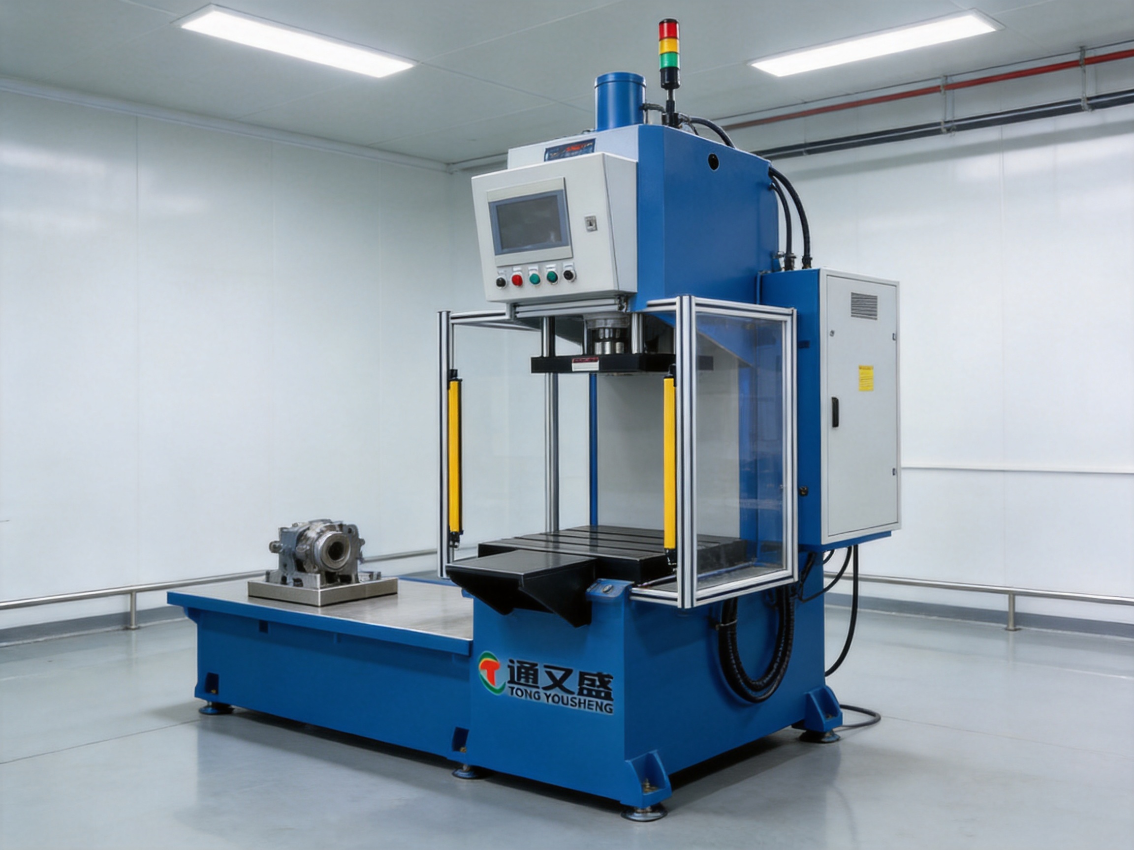
Dual safety light curtains are used to detect entry into hazardous areas around the pressing zone. When an interruption is detected, the control system can stop or inhibit the pressing cycle according to the configured safety logic. The use of light curtains supports safer operation while preserving open access for loading and unloading.
Safety light curtains must be installed, wired, tested, and maintained according to the applicable machine safety requirements. Their effectiveness depends on correct positioning, appropriate resolution, suitable safety distance, and integration with the machine’s emergency stop and control circuits.
Transparent protective doors provide a physical barrier while allowing operators to observe the tooling and workpiece. Visibility is important during setup, troubleshooting, first-piece inspection, and process verification. The doors can be integrated with interlocks so that pressing is prevented when the protective area is not correctly closed.
The combination of physical guarding and optical detection provides a layered safety approach. A machine should not rely on only one safety measure. Mechanical barriers, light curtains, emergency stop devices, operating procedures, warning indicators, and operator training all contribute to safe production.
The three-color indicator light communicates the operating status of the press at a glance. Typical status indications may include ready, running, completed, warning, or fault conditions. Clear visual signaling is especially valuable in busy workshops where operators and supervisors need to understand machine status without opening the control screen.
For automated production lines, the indicator can supplement signals exchanged with a programmable logic controller or manufacturing execution system. The specific color assignment should be defined during commissioning and documented for operators.
The servo press HMI panel provides the interface for entering process parameters, selecting recipes, monitoring machine status, and reviewing alarms. A well-configured HMI allows the operator to adjust authorized settings while protecting critical machine parameters from accidental changes.
A typical operating screen may show target pressure, actual pressure, stroke position, movement speed, dwell time, cycle status, and pass or fail results. Recipe management allows several products to be stored and recalled. This is useful for mixed production, small-batch manufacturing, and product variants that share the same general tooling platform.
The HMI can also support troubleshooting by displaying alarm messages and operating conditions. Clear messages reduce downtime by helping maintenance personnel identify problems more quickly. Depending on the selected control architecture, historical process data may be available for review or export.
Data collection is particularly valuable in industries where traceability is required. A production record may include the model or recipe number, cycle time, peak force, final position, dwell result, alarm status, and pass or fail decision. These records can help manufacturers identify process drift, verify customer requirements, and support continuous improvement.
Automotive chassis parts often require controlled forming, stamping, assembly, and joining. The C-frame press provides access for large components and can be configured for fixtures that hold brackets, supports, bushings, pins, or other chassis-related parts.
For press-fit operations, the machine can control insertion depth and force to help prevent incomplete assembly. For forming operations, the programmed stroke and dwell cycle can support consistent geometry. When combined with a custom fixture and part-present sensors, the press can become part of a semi-automatic or fully automated chassis component line.
Hardware manufacturers commonly require flexible equipment because product sizes, materials, and forming profiles can change frequently. A programmable press allows different parameter sets to be used for different components. The open frame makes it easier to change dies, install fixtures, and handle irregular workpieces.
Controlled speed is important in forming because material behavior can change with movement rate. A slower pressing stage may be used for the final forming operation, while a faster approach and return movement reduces nonproductive time.
Press-fit assembly is one of the most important applications for this machine. Bearings, bushings, shafts, pins, sleeves, connectors, and other components can be inserted under controlled force and displacement.
The machine can be programmed to approach the workpiece quickly, reduce speed before contact, apply the required pressing force, and stop at the specified position. The resulting force-displacement curve can be compared with acceptable process limits. This helps distinguish a correct assembly from a part that is missing, misaligned, damaged, or dimensionally inconsistent.
Riveting quality depends on consistent force, stroke, tool alignment, and material response. The servo hydraulic press can apply a controlled pressing sequence to form the rivet and monitor the resulting process. The tooling can be adapted to different rivet sizes and component configurations.
The supplied application record includes more than 200 riveting projects and a reported riveting strength compliance rate above 98 percent. Actual results depend on material, tooling, rivet design, process parameters, and inspection standards, but this experience demonstrates the company’s familiarity with joining applications.
Powder compacting requires stable pressure application and repeatable displacement control. The machine can be used for laboratory, pilot, or production applications where powder materials must be compressed into a defined shape.
Controlled pressing parameters help reduce variation in density and dimensions. The appropriate tooling, powder preparation method, release system, and cycle configuration should be developed for each material. The press can provide the mechanical force and control platform, while process qualification determines the final production recipe.
Sealing operations often require a specific compression force and dwell time. Excessive force may damage a seal or housing, while insufficient force may produce leakage. The programmable press can control the closing movement and maintain pressure for a defined period.
The company reports more than 500 sealing solutions delivered, with a reported leakage rate as low as 0.1 percent in applicable projects. These figures should be evaluated in relation to the seal type, test method, material, product geometry, and customer acceptance criteria.
The press can be configured for spring testing by moving the spring through controlled displacement points while measuring force. This allows manufacturers to evaluate load characteristics, compression force, return behavior, and consistency between parts.
Spring testing can be used for incoming inspection, in-process verification, final quality control, and development testing. The HMI and data system can be configured to compare measured values with upper and lower limits.
The quality of a servo hydraulic press depends on more than the final assembly. It is influenced by engineering design, material selection, machining accuracy, hydraulic integration, electrical control, software configuration, calibration, and testing. Suzhou Tongyousheng Electronic Technology Co., Ltd. presents itself as an integrated high-technology enterprise covering research and development, production, and sales.
The company uses advanced design software and engineering methods to develop mechanical frames, worktables, actuators, tooling interfaces, hydraulic circuits, electrical cabinets, and safety systems. Three-dimensional design helps engineers identify interference, evaluate service access, and coordinate machine dimensions before fabrication.
Engineering design also considers the relationship between force, stroke, speed, and structural rigidity. A press must not only generate the required force; it must guide that force through the frame and tooling while maintaining acceptable alignment. The hydraulic and control systems must also be matched to the required operating cycle.
High-precision CNC machining centers support the production of critical machine components. Machined surfaces and mounting interfaces influence alignment, actuator installation, tooling repeatability, and long-term stability. Accurate machining is particularly important for parts that transfer pressing force or guide movement.
CNC machining also enables consistent production across multiple machines. When components are manufactured according to controlled drawings and inspection requirements, replacement parts and future equipment can maintain a higher level of compatibility.
Mechanical assembly includes frame construction, actuator installation, table integration, tooling interface preparation, guarding, and adjustment. Assembly personnel must verify alignment, fastening, lubrication, movement clearance, and mechanical travel.
Careful assembly reduces the risk of uneven loading, premature wear, vibration, and inconsistent pressing results. It also supports easier maintenance because components are installed according to a defined structure rather than adjusted informally during final testing.
The hydraulic system supplies the force required for pressing, while the electrical and CNC control systems coordinate machine behavior. Integration involves pumps, valves, cylinders, pressure sensors, position feedback, control cabinets, HMI devices, safety circuits, and communication interfaces.
A well-integrated system must provide stable pressure regulation and predictable movement. It should also respond correctly to emergency stops, protective door switches, light curtain interruptions, sensor faults, and abnormal pressure conditions.
Tongyousheng’s company information identifies algorithmic control software and multi-degree-of-freedom platform linkage systems among its development areas. This broader control expertise is relevant to servo press development because modern pressing equipment increasingly depends on software for motion coordination, parameter management, data analysis, and communication with factory systems.
Software-based control makes it possible to develop application-specific sequences. For example, a press-fit program may use one set of speed and force limits for the approach stage, another for contact detection, and a third for final insertion. The system can then assess the result against defined limits.
Before delivery, a press should undergo functional testing, safety testing, dimensional verification, motion testing, pressure testing, and application-specific validation. The machine may be checked for maximum force, stroke accuracy, speed response, pressure holding, repeatability, alarm behavior, and emergency stop performance.
Factory acceptance testing provides an opportunity to confirm that the equipment meets the agreed technical specification. For customized machines, sample workpieces can be used to verify tooling, process parameters, cycle time, data collection, and product results before shipment.
The main advantage over a conventional manually adjusted hydraulic press is process control. Traditional systems may require an operator to set pressure or position using mechanical stops, manual valves, or visual judgment. The CNC servo hydraulic press provides a more systematic method for controlling and repeating the operation.
A second advantage is flexibility. One machine can support several recipes, tooling configurations, and product variants. This is useful for manufacturers serving multiple customers or producing components in changing batches.
A third advantage is traceability. Force-displacement data and cycle results can support quality management and production analysis. Instead of checking only a sample after the operation, manufacturers can evaluate the process during every cycle or according to a defined sampling plan.
A fourth advantage is accessibility. The C-frame and sliding worktable make it easier to load large workpieces, change tooling, and observe the process. This can reduce handling time and improve operator ergonomics when the machine is properly arranged.
A fifth advantage is integration potential. The machine can be connected to robots, conveyors, sensors, scanners, production databases, and other automation equipment. Its application range therefore extends from standalone manual operation to automated production line integration.
The press can be configured as a standalone workstation or as one station in a larger manufacturing cell. For automated operation, the machine may exchange signals with a robot or programmable logic controller. Typical signals include machine ready, cycle start, cycle complete, fault, part present, safety condition, and pass or fail result.
Linear motion modules can be used to transfer workpieces into and out of the press. Robotic systems can load components, remove completed assemblies, change orientation, or perform inspection. Barcode or radio-frequency identification systems can be used to select the correct recipe for a specific product.
Automation design should consider synchronization, safety zoning, access for maintenance, product orientation, fixture repeatability, and recovery from interrupted cycles. A complete line analysis is required to determine whether the press should use a sliding table, dual fixture arrangement, robotic loading, conveyor transfer, or another handling method.
Because Tongyousheng also develops electric cylinders, linear modules, robotic seventh axes, and motion simulation platforms, the company can apply related motion and control knowledge when developing integrated systems. This allows mechanical and control interfaces to be considered together rather than added after the press has already been completed.
Installation begins with preparing a stable foundation and confirming the machine’s service clearance. The press should be positioned according to the approved layout, anchored where required, and connected to the specified electrical and control services.
Commissioning normally includes checking hydraulic connections, electrical wiring, sensor signals, HMI functions, safety devices, table movement, actuator travel, pressure response, and emergency stop behavior. The initial process recipe should be developed using appropriate tooling and sample workpieces.
Routine maintenance may include checking hydraulic oil condition, inspecting hoses and fittings, verifying sensor operation, lubricating moving interfaces, cleaning the work area, examining tooling wear, and reviewing alarm history. Light curtains and protective door interlocks should be tested at defined intervals rather than assumed to be functional.
Preventive maintenance helps preserve accuracy and reduce unplanned downtime. The schedule should be based on operating hours, cycle frequency, environmental conditions, hydraulic system design, and the recommendations provided during equipment delivery.
The first selection factor is required pressing force. The maximum force should be calculated from the material, interference fit, forming operation, friction, tooling geometry, and safety margin. Trial data or engineering analysis may be necessary for unfamiliar processes.
The second factor is stroke. The selected stroke must cover the approach distance, working movement, tooling compression, and return clearance. A longer stroke may be necessary for large workpieces, but it can influence cycle time and machine dimensions.
The third factor is workpiece and tooling size. The open area, table dimensions, throat clearance, and frame height must accommodate the product and fixture. Customers should provide drawings or three-dimensional models during technical review.
The fourth factor is production speed. The required cycle time should be divided into loading, approach, pressing, dwell, return, unloading, and inspection stages. The machine’s speed range must support the required rhythm without compromising quality.
The fifth factor is data and traceability. If every cycle must be recorded, the control system and communication interface should be specified before purchase. Required data fields, storage period, file format, network architecture, and customer information technology standards should be discussed in advance.
The sixth factor is automation level. A manually loaded machine may need a different fixture, guarding arrangement, and control interface from a robot-loaded press. Early planning prevents costly changes during line integration.
The supplied project information identifies more than 200 press-fit assembly projects with a reported first-pass yield of 99.2 percent. It also identifies more than 150 punching applications with hole diameter tolerance controlled within approximately plus or minus 0.05 mm, more than 200 riveting projects with a reported riveting strength compliance rate above 98 percent, and more than 300 powder compacting cases achieving forming precision of approximately plus or minus 0.02 mm.
These figures illustrate the breadth of application experience associated with the product family. However, machine performance in a specific customer application depends on the workpiece, material, tooling, sensors, calibration, process parameters, environmental conditions, and inspection method. A technical trial remains the best way to confirm final results.
Application engineering is therefore an important part of the purchasing process. The supplier should understand the customer’s product, failure modes, quality limits, cycle time, tooling concept, and production environment. The result should be a press configuration that is technically matched to the process rather than selected solely by nominal tonnage.
Customers requesting a quotation should provide product drawings, material information, pressing direction, required force, stroke, insertion depth, acceptable tolerance, cycle time, workpiece weight, tooling dimensions, and quality inspection requirements.
It is also useful to provide information about the production environment. This may include available electrical power, factory space, ambient temperature, dust or moisture exposure, operator arrangement, communication standards, and existing automation equipment.
For force-displacement applications, sample parts and representative tooling are highly valuable. They allow the supplier to evaluate contact detection, pressing curves, final position, peak force, dwell behavior, and product acceptance criteria.
The main purpose is to perform controlled pressing, forming, assembly, joining, testing, and related force-displacement operations. It is suitable for press-fit assembly, stamping, punching, riveting, sealing, powder compacting, spring testing, and integration into automated lines.
The C-frame provides open access to the working area. This makes it easier to load and unload large or irregular workpieces, inspect tooling, change fixtures, and connect the press with robots or transfer systems.
The CNC system can control and monitor pressure, stroke, speed, dwell time, stopping position, and process sequence. The exact functions depend on the selected configuration and application requirements.
Yes. The HMI-based control system can be configured to store different process parameters for different products or tooling sets. Access permissions can be used to prevent unauthorized changes to important settings.
Yes. The machine is designed for monitoring the relationship between force and displacement. Data recording, storage, export, and factory network communication should be specified according to the customer’s traceability requirements.
The described configuration includes dual safety light curtains, transparent protective doors, and a three-color indicator light. Emergency stops, door interlocks, control safety circuits, and other devices should be confirmed during the technical specification and risk assessment.
The listed model range extends to TYSP-300, which has a maximum pressure of 300 kN. The appropriate model depends on the actual process rather than maximum force alone.
The supplied technical data lists a maximum pressure-maintaining time of 3,000 seconds. The practical dwell time should be selected according to the product, material, tooling, and required production cycle.
Yes. The open structure, programmable control, sliding worktable, and data interface options make it suitable for integration with robots, conveyors, sensors, linear motion modules, and production line control systems.
Selection should consider required force, stroke, working area, tooling size, speed, cycle time, workpiece weight, safety layout, automation method, and data requirements. A technical evaluation using customer samples is recommended for demanding applications.
Yes. Suzhou Tongyousheng Electronic Technology Co., Ltd. develops and manufactures electric cylinders, linear motion modules, linear motor modules, robotic seventh axes, servo press systems, six-degree-of-freedom platforms, and other automation equipment and components.
The C-frame single-column CNC servo hydraulic press machine provides a flexible and precise platform for modern assembly, forming, joining, testing, and production automation. Its open C-frame structure and sliding worktable improve accessibility, while programmable pressure, speed, stroke, dwell time, and stopping position support repeatable processing.
The machine is differentiated from basic hydraulic presses by its CNC control, force-displacement monitoring, recipe management, safety architecture, data traceability, and automation integration potential. The broad TYSP capacity range allows the equipment to serve applications from low-force precision assembly to higher-force stamping and forming.
Its value is further strengthened by the manufacturer’s integrated capabilities in mechanical design, CNC machining, hydraulic and electrical assembly, software development, application engineering, and factory testing. These capabilities support the development of customized press solutions that match specific products, tooling, production targets, and quality requirements.
For manufacturers seeking better process consistency, improved operator access, reliable data collection, and a practical path toward intelligent production, this C-frame CNC servo hydraulic press represents a capable and adaptable equipment solution.
1. Product technical information for the C-Frame Single-Column CNC Servo Hydraulic Press Machine, including model capacity, stroke, speed, dimensions, control functions, and safety configuration.
2. Application records for press-fit assembly, punching, riveting, powder compacting, sealing, and spring testing supplied for product evaluation.
3. General principles of hydraulic press design, force control, displacement monitoring, and industrial forming equipment.
4. General guidance on machine safeguarding, protective guarding, safety light curtains, emergency stop systems, and interlocked access doors.
5. General principles of CNC motion control, industrial automation integration, force-displacement analysis, and manufacturing traceability.
6. Company information concerning research and development, precision CNC machining, automation equipment manufacturing, electric cylinders, linear motion modules, servo presses, and multi-degree-of-freedom motion platforms.
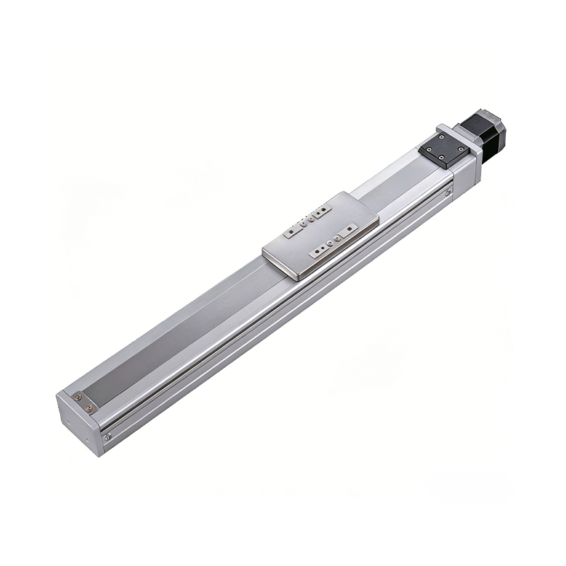 0.01mm High Precision Ball Screw Driven Rail-Embedded Linear Module
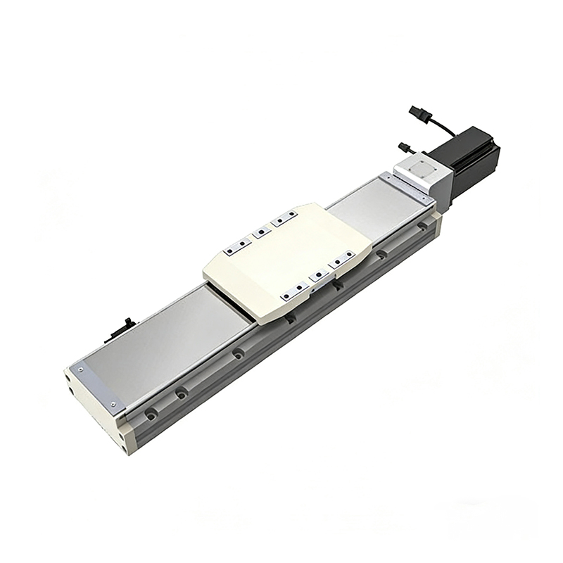 Heavy Load Ball Screw Driven Rail-Embedded Linear Module
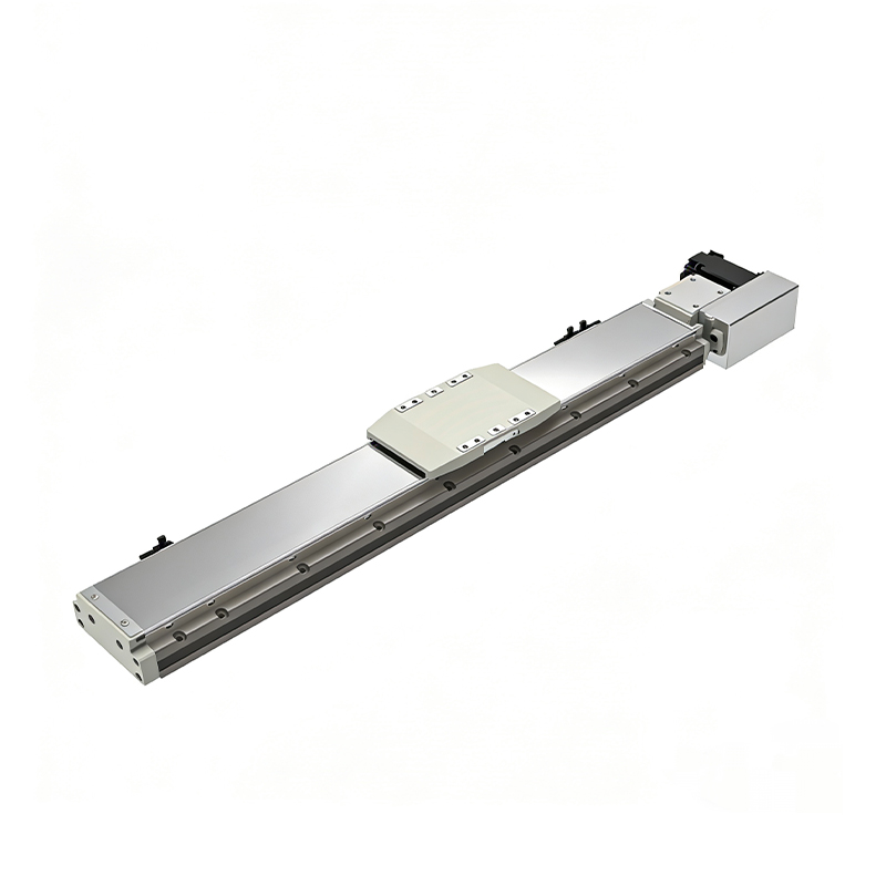 110KG Load Long Stroke Rail-Embedded Linear Module
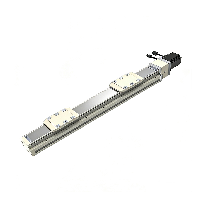 Dual-Slider High Precision Rail-Embedded Linear Module
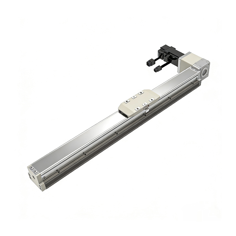 Belt Driven Dust-Proof Rail-Embedded Linear Module
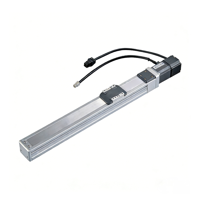 0.01mm High Precision Light Load Ball Screw Linear Module
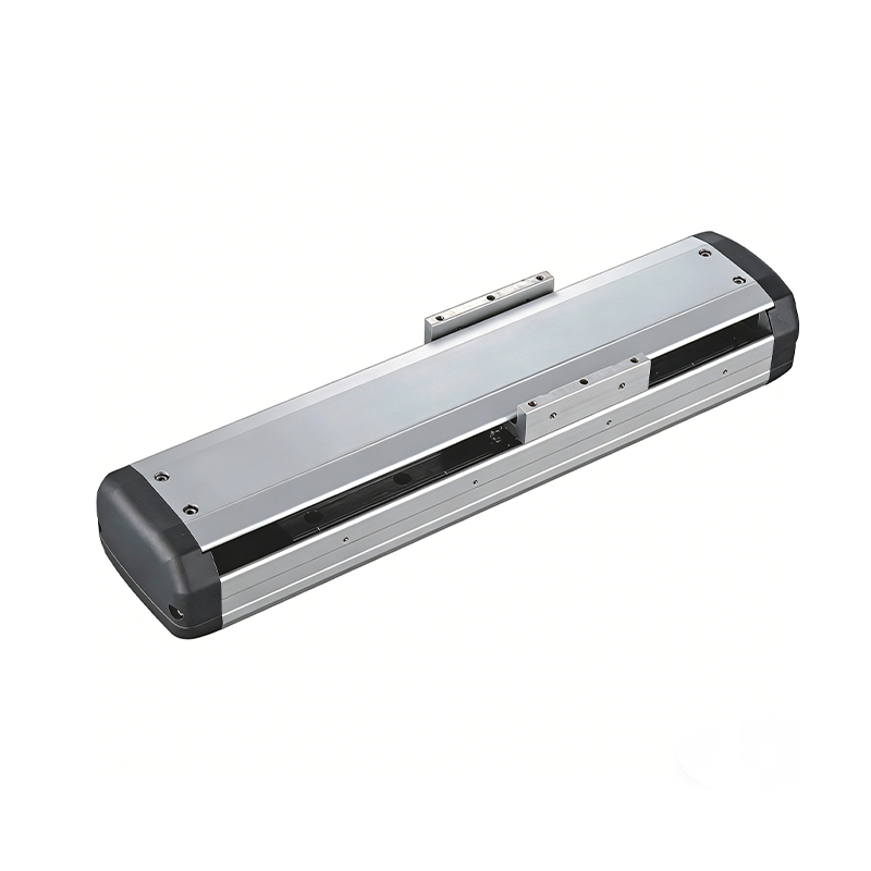 Ball Screw Linear Module with Built-in Sensor
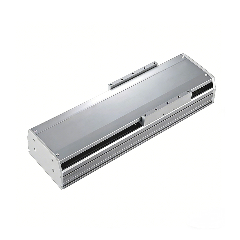 2000mm Long Stroke Ball Screw Linear Module
This 2000mm Long Stroke Ball Screw Linear Module is customized for large-range linear movement automation tasks, support...
READ MOREThis 2000mm Long Stroke Ball Screw Linear Module is customized for large-range linear movement automation tasks, support...
READ MOREThis 2000mm Long Stroke Ball Screw Linear Module is customized for large-range linear movement automation tasks, support...
READ MOREThis 2000mm Long Stroke Ball Screw Linear Module is customized for large-range linear movement automation tasks, support...
READ MORE
If you are interested in our products, please leave us a message. We look forward to providing you with
professional services!
Innovation and transcendence make factory intelligent manufacturing efficient and convenient!
+86 186 2508 0683
19962977901
sales@sz-tys.com
Building 5, Suzhou Mudu International Science and Technology Innovation Park, Jinfeng South Road, Suzhou City, Jiangsu Province, China
