


 English
 Français
 русский
 عربى
عربى Español
 Deutsch
Tel
+86 186 2508 0683

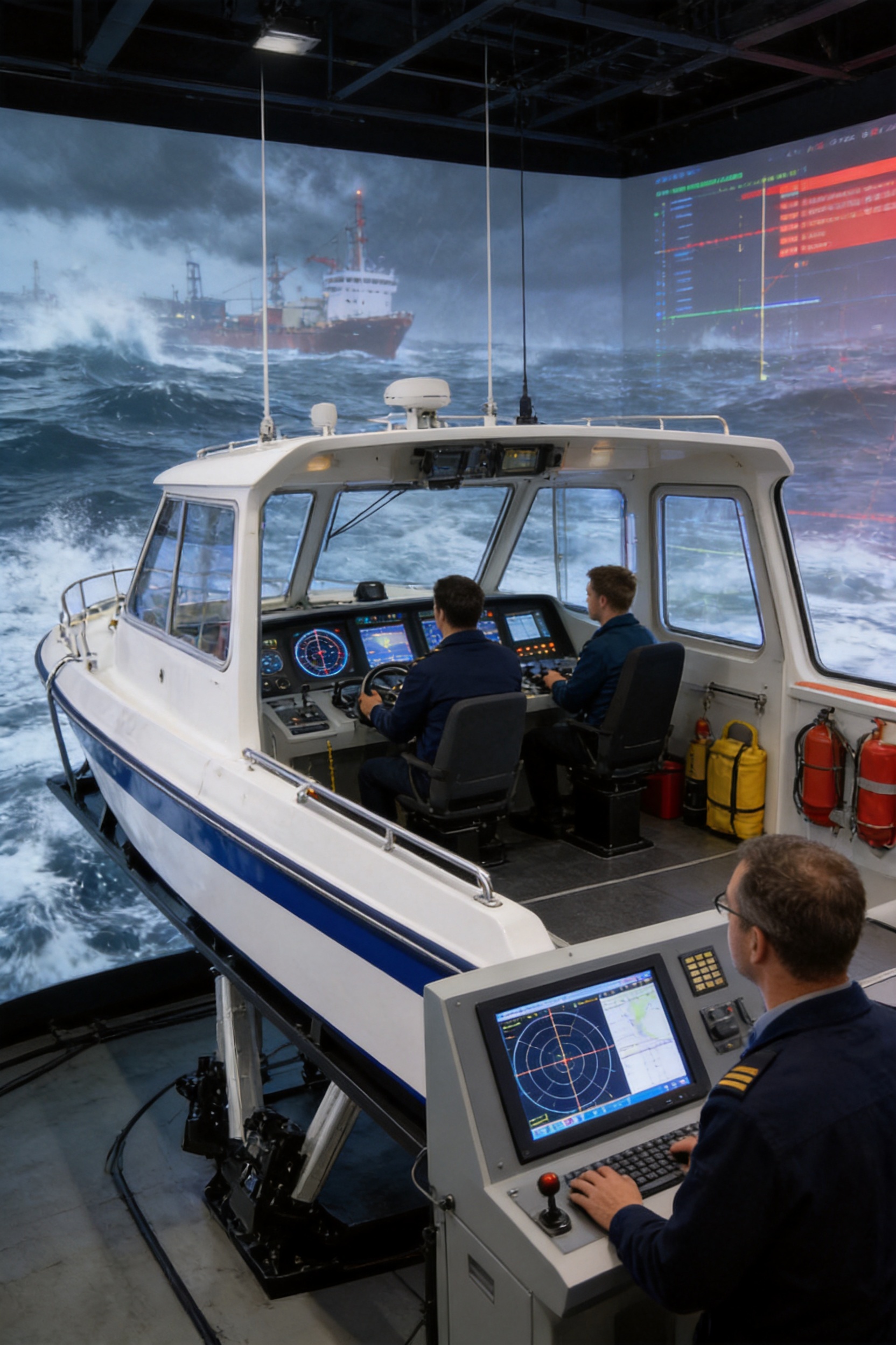
Modern maritime education, ship research, and emergency-response training increasingly depend on simulation systems that can reproduce vessel behavior with accuracy, repeatability, and operational safety. A high-precision vessel simulation platform provides a controlled environment in which operators, students, researchers, and engineering teams can experience the dynamic movement of a vessel without being exposed to the hazards, cost, and unpredictability of real sea conditions.
This platform uses a professional multi-degree-of-freedom motion system to reproduce essential vessel movements, including pitch, roll, yaw, lateral displacement, longitudinal displacement, and vertical lift. By coordinating angular and linear motion, it creates a realistic representation of navigation in waves, during turning, under changing sea states, or in emergency situations. The system is suitable for maritime colleges, navigation training centers, ship research institutions, science museums, and immersive experience venues.
Unlike basic motion systems that produce limited tilting or vibration effects, this platform is designed as a complete motion simulation solution. It combines a rigid mechanical structure, servo-driven electric cylinders, EtherCAT-based control, high-speed communication, motion-control algorithms, and configurable software functions. The result is a responsive and repeatable platform capable of supporting professional training, skills assessment, scientific research, system demonstration, and public education.
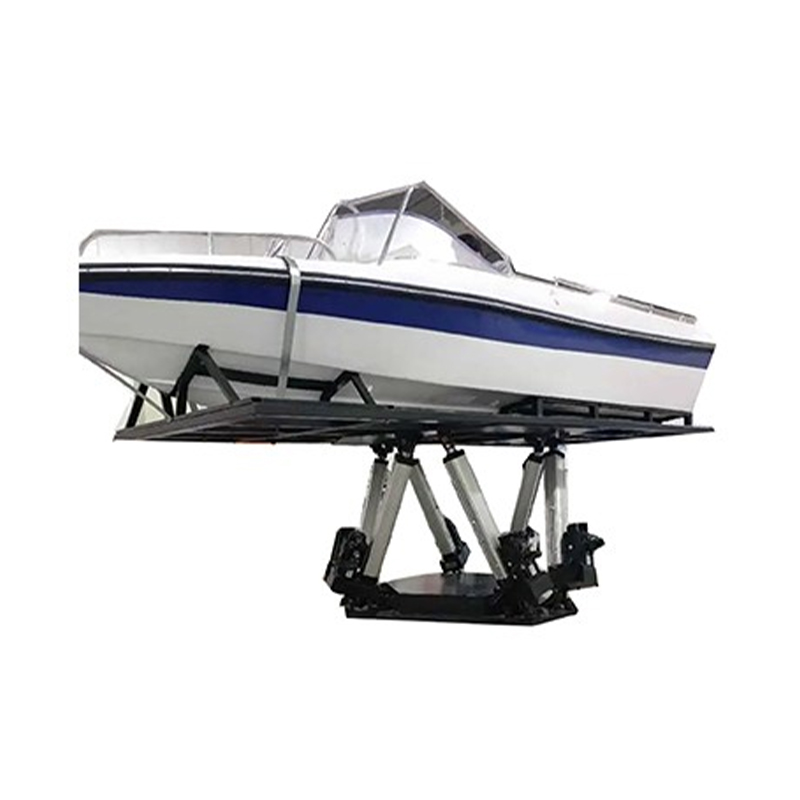
High Precision Vessel Simulation Platform
Ship operators must make decisions while dealing with complex movement, changing visual references, variable acceleration, and uncertain environmental conditions. On a real vessel, these conditions are influenced by waves, wind, loading status, heading, speed, propulsion behavior, and the response of the hull. Training personnel in an actual maritime environment can be expensive and difficult to control, while some emergency scenarios cannot be safely repeated.
A motion simulation platform addresses these limitations by reproducing vessel movement in a controlled indoor environment. The platform can receive programmed motion data or connect with ship control and simulation systems. It then translates the data into coordinated movement across multiple axes. Trainees can practice navigation, equipment operation, emergency response, and decision-making while instructors maintain control over the operating conditions.
The platform also supports research and development. Ship designers and academic institutions can use it to study motion perception, control interfaces, operator workload, and the relationship between simulated vessel movement and digital navigation environments. The ability to repeat the same motion sequence provides a reliable basis for comparison, testing, and performance evaluation.
For museums and immersive venues, the platform creates a more convincing visitor experience than a fixed screen or static cabin. Carefully coordinated pitch, roll, yaw, and translational movement can reinforce visual and audio content, helping users feel the effects of navigation in waves, harbor maneuvering, offshore operations, or severe weather scenarios.
The defining feature of the vessel simulation platform is its ability to generate six fundamental degrees of freedom. Three axes provide angular motion, while three axes provide linear displacement. These motions can be used independently or combined into synchronized movement profiles that reflect the behavior of a vessel at sea.
Pitch is the rotation of the platform around its lateral axis. It represents the bow moving upward and downward relative to the stern. Pitch is particularly important when simulating head seas, acceleration and deceleration, wave approach, and changes in vessel trim.
The platform provides a pitch range of approximately ±5° to ±60°, with a maximum speed of up to 50° per second and acceleration of 100° per second squared. Positioning accuracy and repeat positioning accuracy are specified at 0.03°. This resolution supports gradual wave simulation as well as more pronounced movement profiles for advanced training and demonstrations.
Roll is the rotation around the longitudinal axis and reflects the side-to-side inclination of a vessel. It is one of the most recognizable ship motions and is closely associated with beam seas, turning maneuvers, uneven loading conditions, and stability demonstrations.
The roll axis uses the same general performance range as pitch: approximately ±5° to ±60°, speeds of up to 50° per second, acceleration of 100° per second squared, positioning accuracy of 0.03°, and repeat positioning accuracy of 0.03°. Smooth roll control is essential because abrupt or poorly coordinated movement can reduce realism and create unnecessary discomfort.
Yaw is the rotation around the vertical axis. It represents changes in heading and can be combined with pitch and roll to reproduce turning, course correction, rudder response, and directional changes in a marine environment.
The yaw mechanism offers an angular range of approximately ±5° to ±60°, a speed of up to 50° per second, acceleration of 100° per second squared, and angular positioning accuracy of 0.03°. When connected to a navigation or ship-control environment, yaw movement can help operators understand how heading commands and vessel response relate to the surrounding visual scene.
Lateral displacement moves the platform from side to side along the horizontal transverse axis. This motion can represent lateral drift, side-slip, wave-induced movement, docking operations, and other situations in which the vessel shifts relative to its intended path.
The available lateral displacement is approximately ±10 mm to ±450 mm. The platform can reach speeds of up to 1,000 mm per second, with acceleration of up to 2.0 g. Positioning accuracy is specified at 0.03 mm, while repeat positioning accuracy is 0.01 mm. These specifications allow both small-amplitude precision motion and larger lateral movement for immersive applications.
Longitudinal displacement moves the platform forward and backward. It can be used to represent surge, vessel acceleration, deceleration, stopping behavior, and changes in the relationship between the simulated vessel and the surrounding environment.
The longitudinal axis provides a displacement range of approximately ±10 mm to ±450 mm, a maximum speed of up to 1,000 mm per second, and acceleration of up to 2.0 g. Its positioning accuracy is 0.03 mm, with repeat positioning accuracy of 0.01 mm. Coordinating this axis with pitch can create a more convincing impression of propulsion, braking, wave impact, or sudden changes in vessel speed.
Vertical lift moves the platform upward and downward along the vertical axis. It is especially valuable for simulating heave caused by waves, vessel elevation changes, offshore motion, and intense sea-state conditions.
The vertical axis offers a range of approximately ±10 mm to ±800 mm, a speed of up to 1,000 mm per second, and acceleration of up to 2.0 g. Positioning accuracy is 0.03 mm, and repeat positioning accuracy is 0.01 mm. The larger vertical range gives the system additional flexibility for training platforms, cabin mock-ups, research fixtures, and immersive installations.
The following table summarizes the principal motion performance data provided for the platform. Actual configuration may be adapted according to cabin size, payload, required motion range, application environment, and the interface requirements of the customer’s simulation system.
| Degree of Freedom | Angle or Displacement | Maximum Speed | Acceleration | Positioning Accuracy | Repeat Positioning Accuracy |
|---|---|---|---|---|---|
| Pitch | ±5° to ±60° | Up to 50°/s | 100°/s² | 0.03° | 0.03° |
| Roll | ±5° to ±60° | Up to 50°/s | 100°/s² | 0.03° | 0.03° |
| Yaw | ±5° to ±60° | Up to 50°/s | 100°/s² | 0.03° | 0.03° |
| Lateral Displacement | ±10 mm to ±450 mm | Up to 1,000 mm/s | Up to 2.0 g | 0.03 mm | 0.01 mm |
| Longitudinal Displacement | ±10 mm to ±450 mm | Up to 1,000 mm/s | Up to 2.0 g | 0.03 mm | 0.01 mm |
| Vertical Lift | ±10 mm to ±800 mm | Up to 1,000 mm/s | Up to 2.0 g | 0.03 mm | 0.01 mm |
| System Response Frequency | 0 Hz to 20 Hz | ||||
The combination of angular range, linear travel, speed, acceleration, and precision allows the platform to address multiple application levels. Gentle, low-frequency movement can be used for basic familiarization and public demonstrations. More complex coordinated movement can be used for professional training, control-system testing, and research into human response.
Many conventional training devices focus primarily on visual simulation or provide only a limited tilting function. Such systems may reproduce the appearance of a vessel environment, but they cannot fully communicate the physical relationship between vessel movement, operator posture, control inputs, and visual references.
This platform offers six coordinated degrees of freedom. The addition of lateral, longitudinal, and vertical displacement to pitch, roll, and yaw makes the motion profile more comprehensive. The result is a closer representation of the combined movement that operators experience on an actual vessel.
Training and research require repeatable results. If a platform produces a different movement response each time, it becomes difficult to compare operator performance, evaluate a control algorithm, or identify the effect of a particular scenario. The specified positioning and repeat positioning accuracy provide a foundation for consistent operation.
Repeatability is also valuable for examinations. Instructors can use the same sea-state or emergency sequence for multiple trainees and compare their responses under similar conditions. This is more objective than relying entirely on uncontrolled outdoor training conditions.
With a stated system response frequency of 0 Hz to 20 Hz and linear speeds of up to 1,000 mm per second, the platform can respond to a broad range of programmed motion signals. The servo-driven structure is designed to support both smooth low-speed movement and rapid changes required for advanced simulation.
High dynamic response is particularly important when the motion platform must follow digital wave data, connect with a real-time ship model, or synchronize with a visual and audio environment. Delayed motion can weaken immersion and reduce the training value of a scenario. Accurate timing between the simulated environment and physical movement is therefore a major performance advantage.
Maritime simulation requirements vary considerably. A university training platform may need a compact cabin and moderate payload, while a museum installation may require a larger visitor space and extended daily operating hours. A research institution may prioritize interface flexibility, measurement accuracy, and specialized motion algorithms.
The platform can be configured across a broad range of dimensions, payloads, motor powers, motion ranges, and installation forms. The supplied technical range includes platform sizes from approximately 0.5 to 8 square meters, effective loads from approximately 2,000 to 15,000 kg, and motor power from 400 W to 22 kW. These values indicate that the system can be engineered for different cabin sizes and operational requirements rather than being limited to a single standard model.
Real maritime training involves water, weather, vessel traffic, machinery, and other hazards. A motion platform moves the physical portion of the training into a controlled indoor environment. Instructors can define the scenario, monitor the motion, stop the system when necessary, and repeat the exercise without exposing trainees to the full risks of real operations.
The platform uses a safety-oriented motion-control architecture, servo feedback, and a rigid mechanical structure. Final safety provisions should be determined during project engineering and may include emergency stop devices, mechanical travel limits, protective guarding, access monitoring, software travel limits, overload protection, and operator authorization procedures.
The platform is designed for stable and continuous operation. The supplied specifications state an average trouble-free working time of more than 6,000 hours. The platform also includes a drift specification indicating that after more than 12 hours of continuous operation, the position drift of any individual cylinder will not exceed 0.0025 m under the stated conditions.
These characteristics are important for training centers, museums, and other facilities that may operate the equipment for extended periods. Stable operation reduces interruptions, protects scheduled training sessions, and supports a lower total cost of ownership.
The movement system integrates high-dynamic ball-screw concepts with servo motors and electric cylinders. Compared with systems based on less controllable mechanical actuation, a servo electric cylinder provides accurate position control, controllable velocity, and fast response. It also avoids the need for hydraulic fluid management, which can simplify indoor installation and reduce the possibility of oil leakage.
The electric actuation architecture is suitable for facilities that require clean operation and predictable maintenance. It can be installed in training rooms, research laboratories, education centers, and exhibition spaces where hydraulic equipment may create additional environmental or service requirements.
The technical configuration supports screw diameters from approximately 12 mm to 80 mm, lead screws from approximately 5 mm to 32 mm, and effective travel ranges from approximately 70 mm to 800 mm depending on the model. Rated output is listed from approximately 1 kN to 150 kN, while torque is listed from approximately 1.27 Nm to 140 Nm. These ranges allow the actuator system to be selected according to load, speed, travel, and duty-cycle needs.
Different installation arrangements are available, including front and rear fork hinge, flange, and trunnion configurations. This flexibility helps engineers integrate the cylinders into different frame designs and accommodate the mechanical geometry required for six-axis movement.
Back-drive or direct-connection forms may be selected according to the structure and transmission requirements. The appropriate choice depends on the required force, motion smoothness, mechanical efficiency, mounting constraints, and maintenance plan.
A motion simulator is only as reliable as its mechanical foundation. The high-precision vessel platform uses a high-rigidity frame structure designed to support the moving payload and transfer dynamic forces safely. Structural rigidity helps reduce unwanted deflection, vibration, and alignment errors during rapid movement.
Manufacturing begins with mechanical design and simulation. Engineers can use advanced design software to evaluate frame geometry, actuator placement, load distribution, interference, and service access before production. Proper actuator geometry is particularly important in a multi-degree-of-freedom platform because each cylinder contributes to several combined motion conditions.
After design approval, high-precision CNC machining centers are used to manufacture critical mechanical components. CNC processing improves dimensional consistency and helps maintain the alignment tolerances required by the actuator and hinge assemblies. Machined interfaces can be inspected before assembly so that errors are identified early rather than transferred into the completed platform.
Mechanical components are assembled using controlled procedures. Actuator mounting points, hinge connections, frame joints, and platform interfaces must be checked for correct installation and secure fastening. Alignment verification is essential because even a small geometric error can influence the motion response of a six-axis system.
The manufacturing process also considers serviceability. Components that experience regular load cycles should be accessible for inspection, lubrication, replacement, or adjustment. A well-organized structure reduces maintenance time and helps operators keep the platform in service.
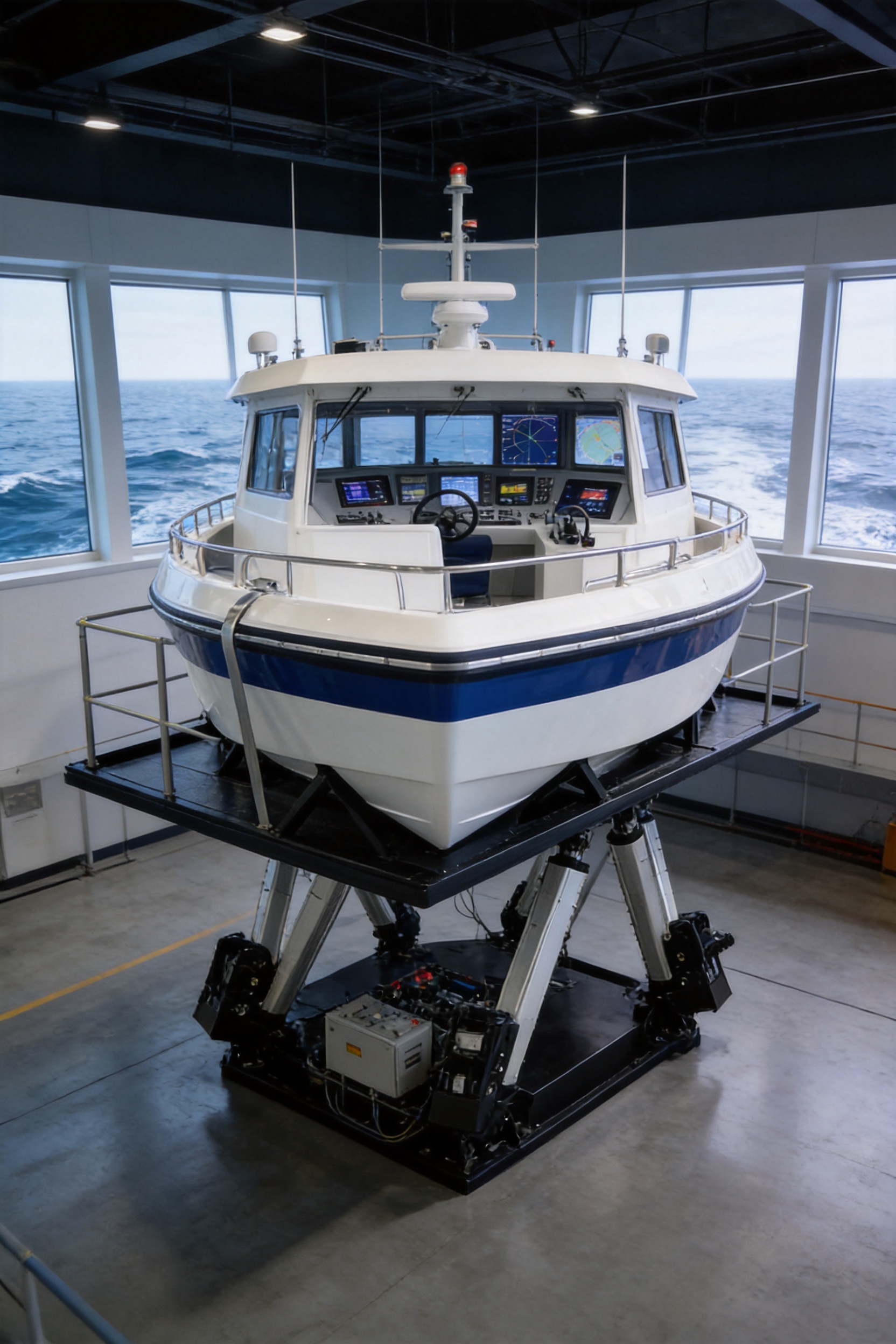
The control system uses an EtherCAT bus architecture. EtherCAT is well suited to coordinated motion because it provides fast communication between the controller, servo drives, feedback devices, and other automation components. In a multi-axis platform, accurate synchronization is essential. If one actuator moves late or responds differently from the others, the platform may produce unwanted vibration or an inaccurate motion path.
The control architecture coordinates the six degrees of freedom as a single motion system. The controller receives target position, velocity, and acceleration information, calculates the required actuator behavior, and distributes commands through the servo network. Feedback from the actuators is used to compare actual movement with the target trajectory.
Core hardware is produced and integrated as part of the company’s automation technology portfolio. This vertical integration can provide advantages in system matching, software development, troubleshooting, and long-term support. Rather than treating the platform as a collection of unrelated components, the system can be engineered as a coordinated mechanical, electrical, and software product.
EtherCAT communication also supports an organized service structure. Engineers can monitor axis status, fault codes, operating parameters, position data, and other information through the control interface. Maintenance teams can use this information to locate abnormal conditions and reduce diagnostic time.
A motion platform must do more than move each actuator to a commanded position. It must transform the desired vessel motion into coordinated actuator displacement while considering platform geometry, velocity limits, acceleration limits, mechanical travel, and safety boundaries. This transformation is commonly known as inverse kinematics or coordinated motion calculation.
The platform uses self-developed core algorithms that have been iteratively optimized. The control software can support non-calibrated operation in the stated configuration, while optional matching algorithms and special-effects modules can be added for customer-specific requirements.
Matching algorithms may be used to connect the physical platform with external ship models, simulation software, visual systems, or control interfaces. Special-effects modules may support programmed wave impact, turning response, acceleration effects, emergency movement, or other scenario-based functions.
Algorithm development is a significant advantage over a platform assembled only from standard motion components. A standard actuator can provide force and travel, but it does not automatically deliver the correct vessel movement. The value of the complete system lies in the coordination among mechanical design, servo control, kinematic calculation, signal processing, and application software.
The vessel simulation platform can support customized sea-state simulation. Instructors or researchers may define motion profiles according to wave direction, wave intensity, vessel heading, operating speed, and scenario duration. These profiles can be used to reproduce calm water, moderate wave conditions, heavy seas, turning movement, sudden impact, or emergency events.
Sea-state simulation should be carefully designed to balance realism and user safety. A realistic platform does not necessarily need to use the largest possible motion range. In many applications, correct timing, acceleration, coordination, and visual synchronization are more important than maximum displacement. The system can therefore be configured for gradual familiarization, professional training, or high-intensity demonstrations.
The software interface can be adapted to the customer’s operational workflow. A training center may require instructor controls, scenario selection, trainee records, and performance review. A research laboratory may require real-time data access, external command input, and motion logging. A museum may prioritize simple operator controls, preset scenes, visitor throughput, and automatic reset functions.
Connection with ship control systems allows the physical motion of the platform to respond to simulated navigation commands. This can help trainees understand the relationship between helm input, engine response, heading, speed, and vessel movement. It also supports the testing of control strategies before they are applied to a real ship or marine system.
Suzhou Tongyousheng Electronic Technology Co., Ltd. integrates research and development, manufacturing, and sales. Its product portfolio includes electric cylinders, linear motion modules, linear motor modules, servo presses, robotic seventh axes, and six-degree-of-freedom motion platforms.
This product background is relevant to the vessel simulation platform because a multi-axis simulator depends on several technologies that are also used in industrial automation. Electric cylinders provide controlled linear motion. Linear modules contribute to accurate positioning. Servo systems deliver dynamic response. Control software coordinates movement. Mechanical engineering ensures that the complete structure operates reliably under load.
The company was established in 2013 and has expanded its product development and manufacturing capabilities over time. Its development history includes linear modules, electric cylinders, servo presses, six-degree-of-freedom platforms, algorithmic control software, and multi-degree-of-freedom linkage systems.
The company maintains an experienced research and development team and uses advanced design software, high-precision CNC machining centers, and patented core technologies. These resources support the design of customized automation equipment rather than limiting customers to catalog products.
Its cooperation with state-owned enterprises, defense technology institutions, and leading universities reflects experience in projects that may require engineering discipline, technical documentation, system integration, and application-specific development. Such cooperation can also encourage the exchange of knowledge between industrial production, academic research, and practical training.
Integrated research and development reduces communication gaps between mechanical, electrical, and software teams. For a motion simulation platform, these disciplines must work together from the beginning. The frame must accommodate the actuator geometry, the actuator must meet the required force and speed, and the software must understand the mechanical limits of the completed system.
Early collaboration also makes it easier to evaluate customization requests. For example, a customer may require a larger cabin but limited floor space, a heavier payload but faster movement, or a specialized control interface connected to existing simulation software. These requirements can affect the frame, motor, transmission, power supply, cooling, control algorithm, and safety design at the same time.
High-precision machining and controlled assembly contribute directly to motion quality. Inaccurate mounting surfaces or inconsistent component dimensions can create backlash, misalignment, uneven loading, or premature wear. CNC machining centers help produce repeatable parts, while inspection and assembly controls help preserve the intended geometry.
The company’s experience with electric cylinders and automation components also supports the selection and integration of motion hardware. The platform can be designed around load capacity, screw diameter, lead, torque, speed, stroke, and installation method rather than relying on a generic actuator selection.
Testing should evaluate the completed platform rather than only individual components. System-level verification may include motion range, speed, acceleration, positioning accuracy, repeatability, synchronization, noise, emergency stopping, continuous operation, and software response.
The stated platform noise level is below 65 dB under the specified conditions. This can be beneficial in classrooms, laboratories, museums, and training centers where excessive mechanical noise could interfere with instruction or reduce the quality of an immersive experience.
Long-duration testing is also important. Continuous operation can reveal thermal effects, actuator drift, communication faults, mechanical loosening, and other issues that may not appear during a short demonstration. The stated operating and drift specifications provide reference points for evaluating long-term stability.
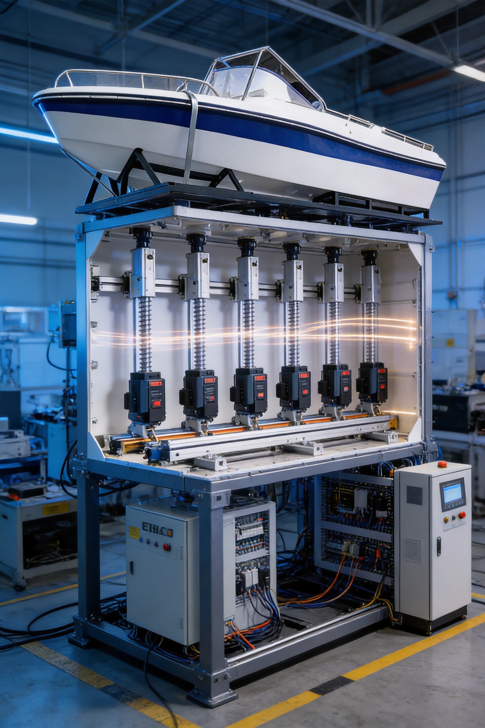
Maritime colleges can use the platform to supplement classroom instruction and practical training. Students can learn how vessel movement affects steering, observation, equipment operation, and emergency response. Instructors can present the same scenario repeatedly and adjust the difficulty according to student progress.
A simulator also allows students to experience conditions that may be difficult to arrange in a training vessel. Heavy rolling, rapid course changes, limited visibility scenarios, and unusual sea states can be introduced in a controlled manner without waiting for suitable weather or risking equipment.
Navigation training centers can use the platform for familiarization, skills assessment, and refresher courses. The repeatability of the system helps centers establish consistent evaluation procedures. Trainees can be assessed on their ability to interpret visual information, respond to changing movement, manage controls, and follow emergency protocols.
Because the platform can connect with ship-control and simulation systems, it can form part of a larger training environment that includes bridge equipment, navigation displays, communications equipment, visual projection, and instructor stations.
Research institutions can use the platform to study ship motion, human-machine interaction, operator response, and control algorithms. Researchers may compare different motion patterns, examine the effect of delay or acceleration, or investigate how physical movement influences performance in a simulated navigation environment.
The controlled and repeatable nature of the platform is useful for experimental work. Test conditions can be recorded, reproduced, modified, and compared. The system can also serve as a hardware-in-the-loop component for evaluating control logic and simulation models.
Science museums can use a vessel simulator to explain ship stability, wave movement, navigation, and marine technology. The platform can be paired with projection, sound, cabin mock-ups, or interactive controls to create an educational experience for visitors.
For public venues, ease of operation, safety, reliability, and maintenance are particularly important. Preset scenarios and controlled motion limits can help operators manage visitor groups while preserving a convincing experience.
Immersive venues can apply the platform to maritime adventures, offshore exploration, naval history, disaster-response scenarios, and other interactive experiences. The wide motion range and multi-axis coordination provide greater flexibility than a fixed simulator or single-axis rocking platform.
Successful installation begins with a clear definition of the payload, cabin dimensions, motion requirements, operating schedule, and software interfaces. The effective load may range from approximately 2,000 kg to 15,000 kg depending on the selected configuration. The platform size may range from approximately 0.5 to 8 square meters.
Engineers must also consider floor structure, anchor points, ceiling height, access paths, maintenance clearance, power supply, ventilation, emergency exits, and user capacity. Supply voltage may be single-phase or three-phase according to the selected motor and system configuration.
The mechanical installation form may use fork hinges, flanges, trunnions, or other connection arrangements. The correct arrangement depends on the actuator direction, frame geometry, load path, required range, and service requirements.
Power selection should reflect not only the maximum movement requirement but also the duty cycle. A platform used occasionally for demonstrations may have different power and thermal requirements from a simulator used continuously for training. Motor power is listed within a broad range of approximately 400 W to 22 kW, allowing the system to be matched to the application.
Commissioning typically includes mechanical inspection, electrical connection, servo tuning, limit verification, coordinate calibration, software configuration, safety testing, and motion-profile validation. Customers should receive operating instructions and maintenance guidance appropriate to the final system configuration.
Regular maintenance helps preserve precision and extend service life. Maintenance activities may include inspection of ball screws, hinges, couplings, fasteners, servo motors, cables, protective devices, and structural connections. The exact schedule should be established according to operating hours, load, motion intensity, environment, and manufacturer recommendations.
Electric cylinders simplify some aspects of maintenance because they do not require hydraulic oil tanks, hoses, pumps, or fluid filtration. However, the ball screw, bearings, seals, and mounting joints still require appropriate inspection and lubrication. Electrical connectors and communication cables should also be checked for secure connection and signs of wear.
Software diagnostics can support preventive maintenance by recording operating hours, fault history, position deviation, overload events, and other system information. Identifying gradual changes early can help prevent unexpected downtime.
The platform’s stated average trouble-free working time of more than 6,000 hours provides a useful reference for reliability planning. Actual service life depends on application conditions and maintenance quality. A properly selected and maintained system can support the long-term operating requirements of professional training and public demonstration facilities.
The competitive value of the high-precision vessel simulation platform comes from the combination of motion capability, customization, control technology, manufacturing resources, and application support. A competitor may offer a motion base, a servo actuator, or a visual simulation package individually. This platform is designed as an integrated solution in which these elements work together.
Its six-degree-of-freedom capability provides a broader physical representation than simple tilt systems. Its precision and repeatability support professional training and research. Its EtherCAT-based architecture supports coordinated multi-axis response. Its self-developed algorithms allow the system to be adapted to customer requirements. Its wide range of load, size, motor, travel, and motion specifications supports different project scales.
The company’s experience across electric cylinders, linear modules, servo presses, and motion platforms further strengthens the solution. The same engineering foundation used to develop industrial automation products can be applied to structural design, actuator selection, control, manufacturing, and service.
Another advantage is the possibility of closer communication during customization. Customers can discuss their payload, movement profile, cabin design, software interface, and safety requirements with a manufacturer that understands both the components and the complete platform. This can reduce integration risk compared with purchasing unrelated subsystems from multiple suppliers.
The platform is therefore suited to organizations that require more than a visual demonstration. It is intended for customers seeking realistic motion, controlled training conditions, engineering flexibility, and a durable system that can support future upgrades.
Maritime simulation requirements continue to develop as digital ship models, virtual reality, augmented reality, artificial intelligence, and real-time data systems become more widely used. A flexible motion platform can serve as the physical foundation for future application development.
Potential expansion may include additional visual systems, synchronized audio, motion cueing algorithms, data logging, instructor dashboards, trainee assessment modules, digital twin connections, remote supervision, and integration with bridge simulators. The platform’s control architecture can be adapted to support these developments when the necessary interfaces are defined during project planning.
Customized motion profiles may also be developed for different vessel types. A small craft, passenger vessel, cargo ship, offshore platform, and naval vessel may have different movement characteristics and training objectives. Software and parameter configuration can help adapt the simulator to the required operating profile.
Research users may require direct access to motion commands, feedback signals, or experimental data. Training users may prefer simplified controls and locked operating limits. The ability to configure the system for different users is an important factor in maximizing its long-term value.
The platform can reproduce pitch, roll, yaw, lateral displacement, longitudinal displacement, and vertical lift. These six degrees of freedom can be controlled independently or combined to represent complex vessel movement under different sea conditions.
Pitch, roll, and yaw are specified within an approximate range of ±5° to ±60°, depending on the final configuration. The actual range selected for a project should consider payload, cabin design, safety limits, motion profile, and application requirements.
Lateral and longitudinal displacement are specified at approximately ±10 mm to ±450 mm. Vertical lift is specified at approximately ±10 mm to ±800 mm. The final travel range depends on the selected electric cylinders, mechanical structure, and required performance.
Yes. The control system is designed to support connection with ship-control and simulation systems. Interface details, communication protocols, signal formats, and software functions should be confirmed during technical planning.
Yes. It is suitable for maritime colleges, navigation training centers, and professional education facilities. It can support navigation practice, movement familiarization, emergency-response training, skills assessment, and instructor-led scenario exercises.
Yes. Its repeatable multi-axis motion, configurable software, servo feedback, and potential for external system integration make it suitable for ship-motion research, human-factor studies, control testing, and hardware-in-the-loop applications.
Electric cylinders can provide precise position and velocity control without hydraulic oil tanks, pumps, hoses, or fluid filtration. They can also support clean indoor installation and simplified maintenance. The appropriate actuator technology should still be selected according to load, speed, duty cycle, and environmental conditions.
Safety is supported through controlled motion algorithms, servo feedback, travel limits, emergency stopping, and system monitoring. The complete safety design should also include project-specific guarding, access control, mechanical limits, operator procedures, and risk assessment.
Yes. Customization may include payload, platform size, angular range, linear travel, motor power, installation method, control interface, motion profile, cabin structure, visual environment, and special-effects software.
Important information includes the payload, cabin or platform dimensions, number of occupants, required degrees of freedom, motion range, maximum speed, acceleration, duty cycle, available floor area, power supply, software interface, installation conditions, and intended application.
Yes. The platform can support immersive maritime demonstrations and educational exhibits. Public applications should use carefully controlled motion profiles, suitable safety devices, durable materials, simple operator controls, and maintenance procedures designed for frequent operation.
Long-term accuracy depends on correct installation, alignment, servo tuning, inspection, lubrication, calibration, and preventive maintenance. Operating data and fault records should be monitored so that drift, wear, or abnormal loading can be addressed before performance is affected.
The high-precision vessel simulation platform provides a comprehensive solution for reproducing realistic maritime movement in a safe and controllable environment. Its six-degree-of-freedom architecture combines pitch, roll, yaw, lateral displacement, longitudinal displacement, and vertical lift. With angular positioning accuracy of 0.03°, linear positioning accuracy of 0.03 mm, repeat positioning accuracy as low as 0.01 mm on linear axes, speeds up to 1,000 mm per second, and a system response frequency of up to 20 Hz, it is designed for demanding simulation requirements.
The platform’s advantages extend beyond its motion specifications. A rigid frame, servo electric cylinders, high-dynamic ball-screw transmission, EtherCAT communication, self-developed algorithms, and customizable software work together as an integrated system. This creates a more realistic, repeatable, and adaptable platform than a basic tilting device or a visually focused simulator without coordinated physical motion.
Suzhou Tongyousheng Electronic Technology Co., Ltd. strengthens the solution through experience in electric cylinders, linear motion products, servo presses, automation equipment, and multi-degree-of-freedom platforms. Its research and development capabilities, CNC machining resources, system integration experience, and application-oriented engineering approach support customized solutions for maritime education, research, training, and immersive demonstration.
For organizations seeking a professional vessel simulation system, the platform offers a practical combination of precision, dynamic response, safety, flexibility, and long-term operating capability. It enables users to reproduce challenging marine conditions, improve operator readiness, study vessel movement, and deliver convincing educational or immersive experiences without relying exclusively on real-sea operations.
1. International Maritime Organization. Standards of Training, Certification and Watchkeeping for Seafarers: Training and Competence Principles.
2. International Maritime Organization. Model Course Materials for Maritime Safety, Navigation, and Simulator-Based Training.
3. International Organization for Standardization. Industrial Automation and Motion-Control System Principles.
4. EtherCAT Technology Group. EtherCAT Communication and Synchronized Motion-Control Concepts.
5. American Bureau of Shipping. Guidance Principles for Marine Simulation and Ship-Handling Training Systems.
6. International Electrotechnical Commission. Functional Safety Principles for Electrical, Electronic, and Programmable Control Systems.
7. International Organization for Standardization. Quality Management Principles for Manufacturing and Engineering Organizations.
8. Product technical specifications and engineering information supplied for the high-precision vessel simulation platform.
9. Corporate engineering and manufacturing information supplied by Suzhou Tongyousheng Electronic Technology Co., Ltd.
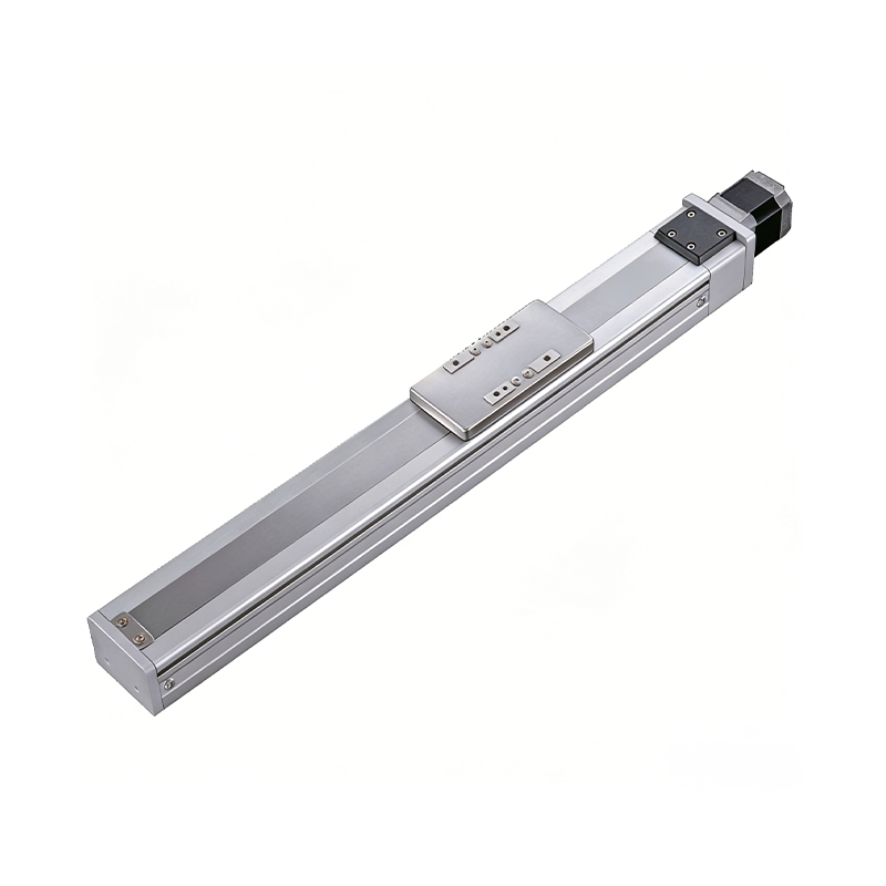 0.01mm High Precision Ball Screw Driven Rail-Embedded Linear Module
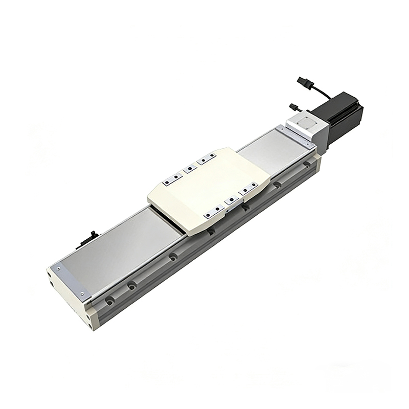 Heavy Load Ball Screw Driven Rail-Embedded Linear Module
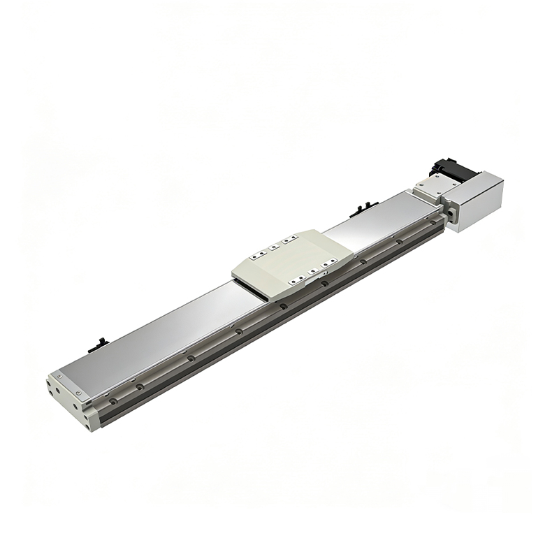 110KG Load Long Stroke Rail-Embedded Linear Module
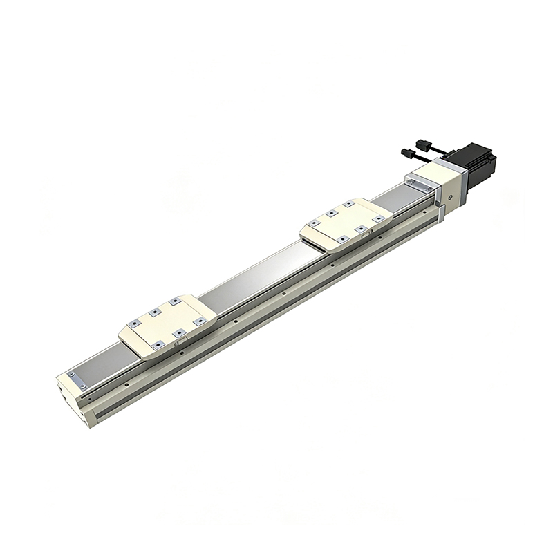 Dual-Slider High Precision Rail-Embedded Linear Module
 Belt Driven Dust-Proof Rail-Embedded Linear Module
 0.01mm High Precision Light Load Ball Screw Linear Module
 Ball Screw Linear Module with Built-in Sensor
 2000mm Long Stroke Ball Screw Linear Module
This 2000mm Long Stroke Ball Screw Linear Module is customized for large-range linear movement automation tasks, support...
READ MOREThis 2000mm Long Stroke Ball Screw Linear Module is customized for large-range linear movement automation tasks, support...
READ MOREThis 2000mm Long Stroke Ball Screw Linear Module is customized for large-range linear movement automation tasks, support...
READ MOREThis 2000mm Long Stroke Ball Screw Linear Module is customized for large-range linear movement automation tasks, support...
READ MORE
If you are interested in our products, please leave us a message. We look forward to providing you with
professional services!
Innovation and transcendence make factory intelligent manufacturing efficient and convenient!
+86 186 2508 0683
19962977901
sales@sz-tys.com
Building 5, Suzhou Mudu International Science and Technology Innovation Park, Jinfeng South Road, Suzhou City, Jiangsu Province, China
