


 English
 Français
 русский
 عربى
عربى Español
 Deutsch
Tel
+86 186 2508 0683

Vehicle development is increasingly dependent on accurate, repeatable, and data-driven testing. Modern vehicles must perform safely and predictably during acceleration, braking, cornering, lane changes, emergency avoidance, uneven-road travel, and a wide range of driver inputs. Testing these conditions exclusively on public roads or proving grounds can be expensive, time-consuming, difficult to reproduce, and limited by safety considerations. A six-degree-of-freedom vehicle dynamic simulation test platform provides an efficient alternative by reproducing complex vehicle motion in a controlled laboratory environment.
The 6DOF Vehicle Dynamic Simulation Test Platform described in this article is designed for professional automotive dynamic testing, chassis development, control-system validation, driver behavior research, and engineering verification. Through coordinated pitch, roll, yaw, lateral, longitudinal, and vertical motion, the platform recreates the essential movement characteristics that a vehicle experiences in real driving conditions. Its high-precision electric actuation system, EtherCAT-based control architecture, heavy-duty mechanical structure, and adaptable software environment allow engineering teams to evaluate vehicle behavior with improved repeatability and reduced testing risk.
Unlike a basic motion table intended for simple vibration or positioning tasks, this platform is a complete motion simulation system. It combines precision mechanical transmission, servo control, multi-axis coordination, motion-model processing, safety protection, and software compatibility in one integrated solution. The result is a powerful development tool for automotive manufacturers, universities, research institutes, motorsport organizations, intelligent vehicle developers, and suppliers of chassis, suspension, steering, braking, and driver-assistance systems.
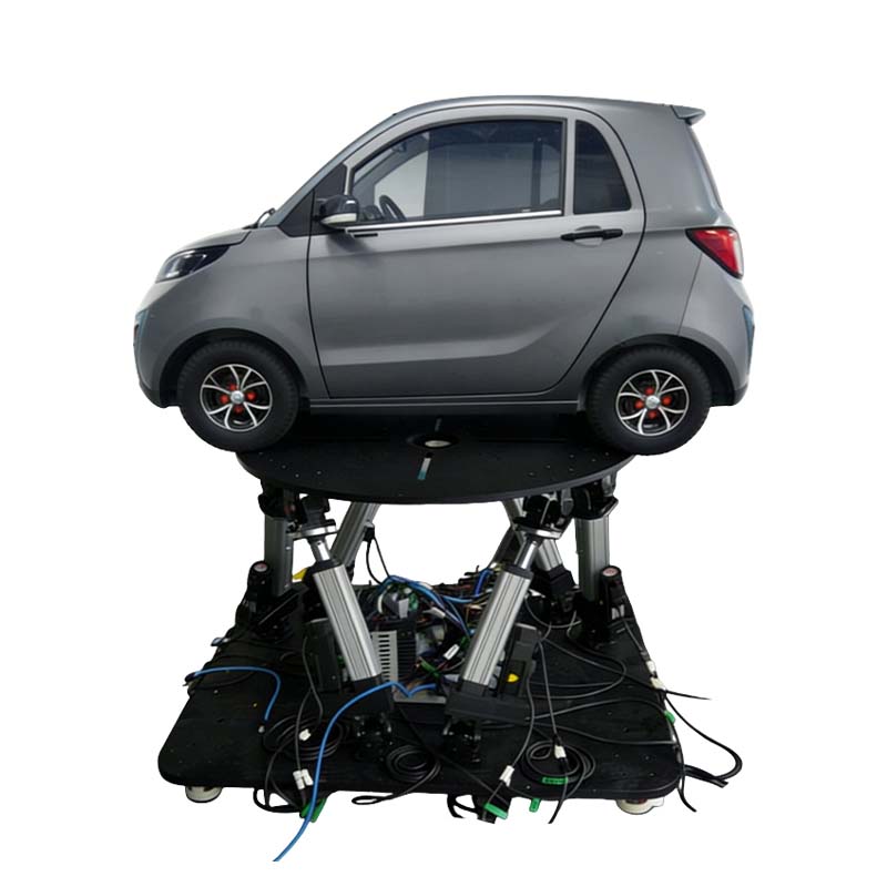
6DOF Vehicle Dynamic Simulation Test Platform
A six-degree-of-freedom platform is a parallel or multi-axis motion system capable of controlling six independent movement components. These components are generally divided into three rotational axes and three translational axes. The rotational axes are pitch, roll, and yaw. The translational axes are lateral displacement, longitudinal displacement, and vertical lift.
Pitch represents rotation around the lateral axis and is associated with vehicle nose-up and nose-down motion during acceleration, braking, ramps, and changes in road gradient. Roll represents rotation around the longitudinal axis and is associated with body movement during cornering, road banking, and uneven lateral loading. Yaw represents rotation around the vertical axis and is associated with directional changes, steering response, vehicle heading, and rotation during emergency maneuvers.
Lateral displacement moves the simulated vehicle toward the left or right. Longitudinal displacement moves it forward or backward. Vertical lift raises or lowers the platform to reproduce changes in road elevation, suspension movement, bumps, dips, and other vertical conditions. When these six axes are coordinated precisely, the platform can reproduce complex combinations of motion instead of isolated single-axis movements.
For vehicle engineering, coordinated motion is essential. A real vehicle rarely experiences only one movement at a time. During a sudden lane change, for example, the vehicle may experience yaw, roll, lateral acceleration, suspension loading, and vertical movement simultaneously. During hard braking on an uneven surface, pitch, vertical displacement, wheel-load transfer, and steering corrections may occur together. A six-axis platform enables these combined events to be recreated and repeated under controlled conditions.
The platform can be configured with different travel ranges, speeds, acceleration capabilities, payload capacities, and control strategies according to the application. This makes it suitable for passenger vehicles, commercial vehicles, electric vehicles, autonomous vehicle prototypes, vehicle seats, cockpit modules, chassis systems, and specialized research rigs.
The system supports angular and linear motion ranges that can be selected according to test requirements. Its representative specifications include angular ranges from ±5° to ±60° for pitch, roll, and yaw, and linear displacement ranges from ±10 mm to ±450 mm for lateral and longitudinal movement. The vertical axis can provide a displacement range from ±10 mm to ±800 mm. These ranges allow the platform to be adapted to both precise laboratory simulation and larger-scale vehicle dynamic testing.
| Motion Axis | Representative Range | Maximum Speed | Acceleration | Positioning Accuracy | Repeat Positioning Accuracy |
|---|---|---|---|---|---|
| Pitch | ±5° to ±60° | Up to 50°/s | 100°/s² | 0.03° | 0.03° |
| Roll | ±5° to ±60° | Up to 50°/s | 100°/s² | 0.03° | 0.03° |
| Yaw | ±5° to ±60° | Up to 50°/s | 100°/s² | 0.03° | 0.03° |
| Lateral Displacement | ±10 mm to ±450 mm | Up to 1000 mm/s | Up to 2.0 g | 0.03 mm | 0.01 mm |
| Longitudinal Displacement | ±10 mm to ±450 mm | Up to 1000 mm/s | Up to 2.0 g | 0.03 mm | 0.01 mm |
| Vertical Lift | ±10 mm to ±800 mm | Up to 1000 mm/s | Up to 2.0 g | 0.03 mm | 0.01 mm |
The listed values represent a flexible product range rather than a single fixed configuration. Final performance depends on payload, platform dimensions, actuator selection, motion profile, structural design, and test objectives. During technical consultation, the supplier can match the platform configuration to the vehicle mass, center of gravity, desired frequency response, required travel, and installation environment.
A major benefit of the platform is its ability to reproduce driving conditions in a repeatable way. Engineers can create predefined scenarios, replay measured vehicle data, or generate motion commands from mathematical vehicle models. The system can be used to simulate acceleration, braking, cornering, emergency lane changes, obstacle avoidance, bumpy roads, road undulations, incline transitions, and combined maneuvers.
In acceleration testing, the platform can produce longitudinal motion and pitch behavior that represent weight transfer toward the rear of the vehicle. During braking tests, the system can recreate forward weight transfer, nose dive, and changes in vehicle attitude. For cornering evaluation, coordinated roll, yaw, and lateral movement can be used to reproduce steering inputs and lateral load transfer.
Uneven-road testing requires careful coordination of vertical motion with pitch and roll. A platform that simply moves vertically cannot fully represent the body attitude changes caused by a real road surface. By controlling multiple axes together, the six-degree-of-freedom system can generate more representative motion patterns for seat comfort evaluation, suspension calibration, human-machine interaction research, and autonomous driving development.
Emergency maneuvers are particularly valuable in a controlled test environment. Sudden steering inputs, rapid changes in yaw rate, combined braking and turning, and obstacle-avoidance events can be tested repeatedly without exposing a vehicle, driver, or test personnel to the same risks encountered on an open proving ground. Repeated trials also improve the quality of comparative analysis because each test can use the same initial conditions and motion sequence.
The platform uses electric cylinders and servo-driven linear motion components as the primary actuation technology. Compared with conventional hydraulic systems, an electric architecture can provide clean operation, accurate positioning, simplified maintenance, and convenient integration with digital control systems. It avoids hydraulic oil leakage and reduces the infrastructure normally associated with pumps, reservoirs, valves, and hydraulic power units.
The actuator design integrates a high-dynamic ball screw concept with servo motor control. A ball screw converts rotary motor motion into precise linear movement while maintaining efficient transmission and high positioning capability. The actuator can be selected with different screw diameters, leads, motor powers, output forces, and stroke lengths to meet the needs of different platform sizes and payloads.
Representative technical ranges include screw diameters from approximately 12 mm to 80 mm, lead screw values from approximately 5 mm to 32 mm, rated output forces from approximately 1 kN to 150 kN, and rated speeds from approximately 133 mm/s to 1000 mm/s. Motor power can range from approximately 400 W to 22 kW, while effective load capacity can be configured from approximately 100 kg to 5000 kg depending on the selected structure and actuator arrangement.
High-quality mechanical transmission is important because motion accuracy depends not only on software commands but also on stiffness, backlash control, bearing selection, screw precision, joint design, and structural alignment. The platform is therefore developed as a coordinated electromechanical system rather than a collection of independent actuators.
The electric actuator approach also supports flexible installation. Depending on the application, actuators can be configured with front and rear fork hinges, flange connections, trunnion arrangements, or other customized mechanical interfaces. These connection options allow the system to be adapted to different base structures, vehicle fixtures, platform frames, and laboratory layouts.
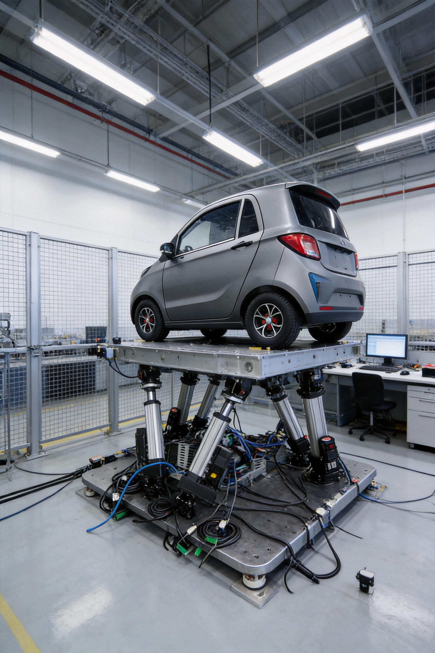
The control system uses an EtherCAT bus architecture to coordinate the servo axes. EtherCAT is designed for high-speed industrial communication and is well suited to applications that require synchronized movement, short communication cycles, and reliable real-time data exchange. In a six-axis motion platform, synchronization is essential because even small timing differences between actuators can affect the accuracy and smoothness of the simulated vehicle movement.
The control architecture includes servo motors, servo drives, motion controllers, feedback devices, platform control software, and safety-related components. The controller processes the desired motion trajectory and distributes synchronized commands to the individual axes. Feedback from encoders and other sensors is used to monitor actual position, speed, and system status.
The system is designed to support high-frequency response and precise position control. Its representative system response frequency is specified at 0 Hz to 20 Hz, depending on the final configuration and motion requirements. This response range supports many vehicle dynamic simulation tasks, including low-frequency body movement, handling events, road input reproduction, and controlled human-factor studies.
Platform control software can be configured for different operating modes. Operators may select manual positioning, programmed trajectories, replayed test profiles, real-time external commands, or special-effects modules. The software can also support parameter adjustment, axis monitoring, motion status display, alarm management, test recording, and scenario switching.
A notable feature is the use of self-developed core algorithms. These algorithms are intended to simplify platform operation, reduce calibration requirements in suitable operating conditions, and improve the relationship between the commanded trajectory and the actual platform movement. The control strategy can be refined through iterative engineering, application feedback, and testing under different payload and motion conditions.
Optional matching algorithms can be added for specific customer requirements. These may include vehicle motion-model matching, special-effects generation, synchronization with external simulation software, real-time data conversion, or customized test sequence management. The exact software configuration should be defined during the technical design stage because different research tasks require different signal formats, sampling rates, and control interfaces.
The platform offers several practical advantages compared with testing only on roads, proving grounds, or basic single-axis motion equipment. The most important advantage is repeatability. Once a test profile has been defined, the same movement can be reproduced multiple times with consistent initial conditions. This is useful for comparing control software revisions, suspension settings, steering maps, tire characteristics, and driver responses.
Another advantage is laboratory safety. High-risk vehicle maneuvers can be studied in a controlled environment before full-scale road testing. Researchers can evaluate emergency responses, control strategies, and human reactions while reducing exposure to traffic, weather, road hazards, and unpredictable external variables. The platform does not replace all proving-ground testing, but it can make the overall development process more efficient by identifying issues earlier.
Compared with conventional hydraulic motion platforms, the electric configuration offers a cleaner working environment and may simplify installation and maintenance. Electric drives can be monitored digitally, and motion parameters can be integrated directly into an industrial communication network. The absence of hydraulic fluid and large hydraulic power equipment can also reduce the complexity of laboratory planning.
Compared with simple electric linear stages, the 6DOF system provides coordinated multi-axis motion and substantially greater application depth. A linear stage may deliver accurate travel along one axis, but vehicle dynamic simulation requires simultaneous control of rotational and translational motion. The six-axis platform is designed specifically for this coordinated movement problem.
Compared with fixed mechanical test rigs, the platform provides greater flexibility. Test profiles can be changed through software rather than requiring a new physical fixture for each scenario. The same platform can be used for different vehicle models, seating arrangements, research programs, or control-system evaluations when suitable fixtures and payload conditions are provided.
| Evaluation Factor | 6DOF Electric Simulation Platform | Basic Single-Axis Stage | Road or Proving-Ground Test |
|---|---|---|---|
| Motion capability | Coordinated pitch, roll, yaw, and three linear axes | Usually limited to one or a few axes | Natural vehicle motion in real surroundings |
| Repeatability | High, based on programmed motion profiles | High for the supported axis or axes | Affected by weather, surface, traffic, and driver variation |
| Safety control | Controlled laboratory environment with protective functions | Generally manageable for low-energy tests | Requires extensive operational and site safety measures |
| Test flexibility | Profiles and parameters can be changed in software | Suitable for focused motion tasks | Requires physical route or surface changes |
| Data comparison | Consistent conditions support direct comparison | Good for component-level testing | Highly representative but less controlled |
| Installation and cleanliness | Electric drive with no hydraulic oil circuit | Usually compact and electrically driven | Requires vehicle, site, logistics, and environmental support |
The practical value of the platform lies in combining the strengths of laboratory repeatability with multi-axis vehicle motion. It can be used early in development for concept evaluation and later for validation, calibration, and regression testing.
A vehicle simulation platform must carry significant static and dynamic loads. The frame must resist deformation while allowing the actuators to generate rapid coordinated movement. Structural stiffness affects positioning accuracy, resonance behavior, vibration transmission, and the platform’s ability to reproduce the intended motion profile.
The platform is designed with a heavy-duty frame suitable for demanding automotive applications. The frame, joints, actuator supports, vehicle fixtures, and safety structures must be considered together. A strong structure helps maintain geometric accuracy when the payload changes or when dynamic forces act on the system during acceleration and deceleration.
Mechanical design begins with an understanding of the required payload, center-of-gravity position, motion envelope, actuator force, frequency response, and mounting conditions. Engineering software can be used to model the platform assembly, evaluate interference, analyze load paths, and optimize component dimensions before manufacturing. This design stage is particularly important for large platforms with high travel and high payload requirements.
The system can be built in different sizes, with representative platform areas ranging from approximately 0.3 square meters to 6 square meters. A compact version may be appropriate for a seat, cockpit, or component test. A larger version can be designed to support a full vehicle body, cabin module, or specialized automotive test structure. The final size depends on the vehicle dimensions and the desired test configuration.
Installation arrangements may include front and rear fork hinges, flanges, trunnions, or application-specific connection systems. These options help engineers integrate the platform into a test cell while maintaining the required motion geometry. Proper foundation design, leveling, anchoring, access clearance, and cable routing should be included in the installation plan.
The performance of a motion platform depends heavily on manufacturing quality. Precision control is required for machined parts, screw assemblies, actuator housings, joint interfaces, motor mounts, sensor brackets, and the overall frame. Small errors in alignment can become more significant when multiple actuators work together across a large motion envelope.
Suzhou Tongyousheng Electronic Technology Co., Ltd. combines product research and development, manufacturing, engineering integration, and technical sales. The company has advanced design software, high-precision CNC machining centers, and an experienced research and development team. These resources support the development of electric cylinders, linear motion modules, linear motor modules, servo presses, robotic seventh axes, and six-degree-of-freedom platforms.
In the production process, mechanical components can be designed and reviewed digitally before machining. CNC machining supports consistent dimensions and repeatable production of precision parts. Critical surfaces can be inspected after machining, while assembly procedures can be used to verify alignment, fastener condition, transmission smoothness, and sensor installation.
Actuator assembly requires particular attention to screw installation, bearing preload, lubrication, encoder alignment, coupling accuracy, and end-of-stroke protection. Servo motors and drives must be matched to the actuator load and dynamic requirements. Factory testing may include no-load operation, loaded movement, position accuracy checks, repeatability evaluation, speed verification, emergency-stop testing, and long-duration running.
The company’s manufacturing capability is supported by experience in industrial automation and motion-control equipment. This is important because a vehicle simulation platform is not simply a welded structure with motors. It requires coordinated expertise in mechanical design, electrical engineering, embedded control, servo tuning, industrial communication, software development, safety engineering, and application support.
The company also reports cooperation with state-owned enterprises, defense technology institutions, and universities. Such cooperation can help expand the range of testing requirements considered during product development. Research-oriented customers often require customized motion profiles, special interfaces, advanced data acquisition, and long operating cycles. Experience with these environments can strengthen the platform’s ability to support demanding engineering programs.
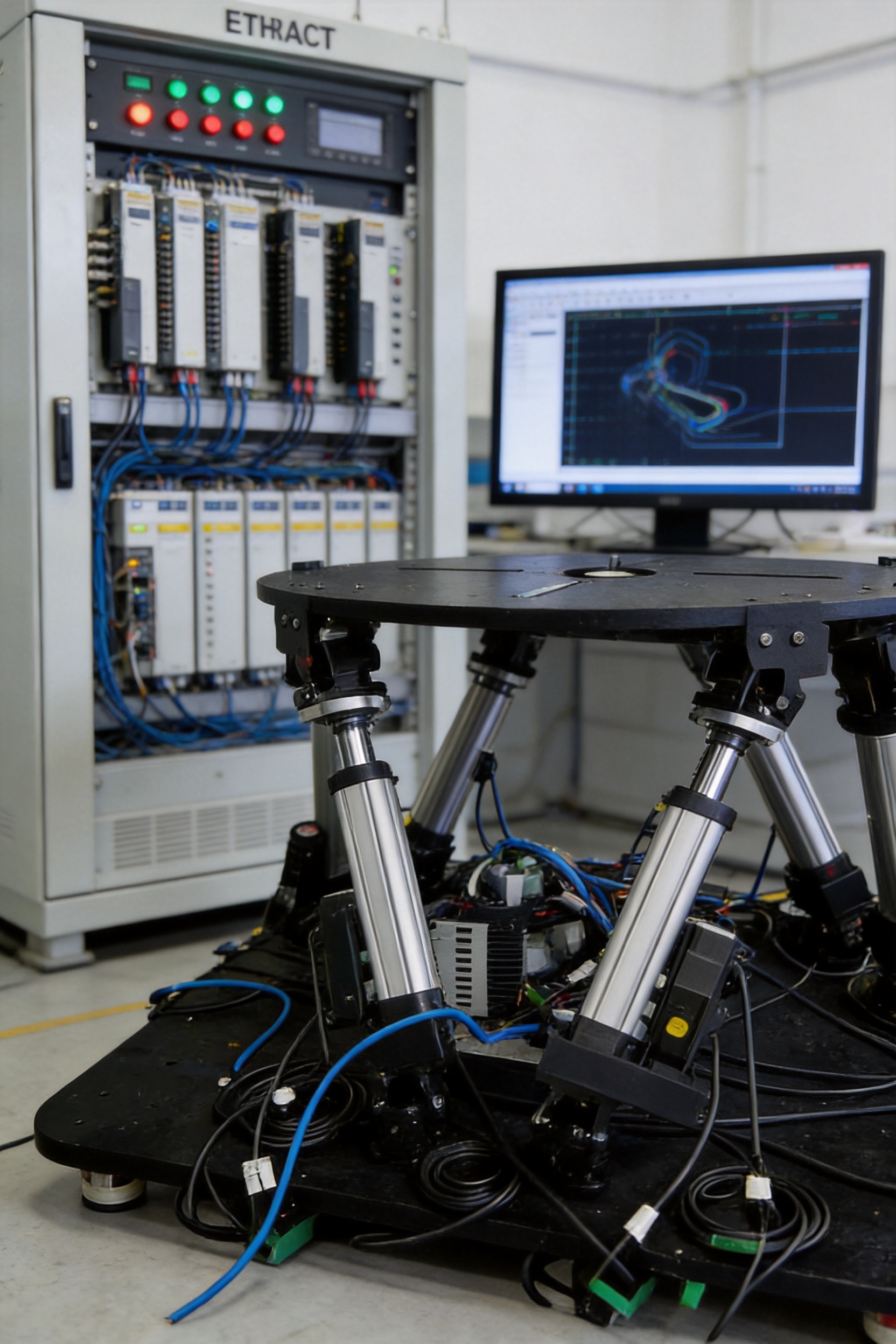
Positioning accuracy and repeat positioning accuracy are important when a platform is used for component comparison, software calibration, or research measurement. Representative angular positioning accuracy is 0.03°, with repeat positioning accuracy of 0.03°. For linear axes, representative positioning accuracy is 0.03 mm, with repeat positioning accuracy of 0.01 mm.
These values provide a basis for evaluating motion quality, but actual performance must always be confirmed according to payload, test speed, acceleration, mounting condition, temperature, and measurement method. A platform operating at high speed with a heavy vehicle payload will have different dynamic behavior from a platform operating at low speed with a light research fixture.
The technical information also specifies a run-parameter value of no more than 0.02 mm and a long-duration drift target in which the position drift of any one cylinder does not exceed 0.0025 m during continuous operation of more than 12 hours. Long-duration stability is valuable for endurance tests, automated overnight programs, repeated software verification, and research experiments that require consistent positioning over extended periods.
Reliability is supported by the selection of industrial servo components, robust mechanical interfaces, protection against overtravel, monitoring of abnormal operating conditions, and appropriate maintenance procedures. The reported average trouble-free working time for the broader actuator product range is greater than 6000 hours. The actual service life of a complete platform depends on duty cycle, payload, acceleration, environment, lubrication, inspection, and operating practices.
For demanding applications, preventive maintenance should include checking screw lubrication, joint wear, fastener torque, cable movement, encoder feedback, emergency-stop circuits, structural connections, and software alarms. A scheduled maintenance plan can reduce unexpected downtime and help preserve motion accuracy.
Safety is essential because a six-axis platform may move a heavy payload at high speed and acceleration. The system should be installed with suitable guarding, access control, emergency-stop devices, warning signals, travel limits, software limits, mechanical stops, and load-appropriate fixtures. The exact safety package should be determined through a risk assessment for the intended test cell.
The platform’s control system can monitor axis position, servo status, communication condition, overload condition, and abnormal feedback. If a fault is detected, the system can initiate a controlled stop or emergency stop according to the severity of the event and the safety design. Safety functions should be verified during commissioning and periodically inspected afterward.
Vehicle or component fixtures must be designed to prevent unwanted movement during testing. The fixture should account for static weight, dynamic force, center of gravity, attachment points, vibration, and possible emergency-stop loads. For driver-in-the-loop applications, additional measures may include restraint systems, padded surroundings, access platforms, operator observation, and clear procedures for entering and leaving the test area.
Safety does not depend solely on software. Mechanical design, electrical protection, operator training, installation quality, maintenance, and documented test procedures are all necessary. A professional supplier should provide technical support for platform integration, commissioning, and operating guidance.
Chassis engineers can use the platform to evaluate suspension response, body motion, steering behavior, and vehicle attitude under controlled motion inputs. Repeated profiles can be used to compare spring and damper settings, active suspension algorithms, anti-roll strategies, bushing designs, and control parameters.
The platform can help identify undesirable body movement, delayed response, excessive roll, pitch sensitivity, or control instability before final road validation. It can also support the development of test procedures for new electric vehicle platforms, where battery mass and a lower center of gravity may change handling characteristics.
Steering systems can be evaluated during simulated lane changes, cornering, rapid direction changes, and emergency maneuvers. Braking development may involve acceleration and pitch profiles that reproduce weight transfer and vehicle attitude changes. The repeatable environment allows engineers to compare brake-control software, regenerative braking strategies, electronic stability functions, and combined braking-and-steering behavior.
When connected to a suitable visual, auditory, and vehicle-control environment, the platform can support driver-in-the-loop studies. Researchers can examine driver reaction, steering behavior, workload, comfort, perception of vehicle motion, and responses to unexpected events.
Because the same motion sequence can be repeated, different drivers or control systems can be compared under similar conditions. The platform may also support studies of motion cues, simulator sickness, human-machine interaction, and the relationship between displayed road scenes and physical vehicle movement.
Autonomous driving systems must respond to changing vehicle dynamics, road conditions, and control commands. A motion platform can provide controlled inputs for testing perception-to-control pipelines, trajectory planning, vehicle stability, and fault response. It can also be integrated with simulation software to create repeatable scenarios that would be difficult to reproduce on a physical road.
For advanced driver-assistance systems, the platform may be used to assess lane-change behavior, emergency braking response, steering assistance, driver override, and transitions between automated and manual control. Integration requirements vary, so the control interface and data architecture should be specified at the beginning of the project.
The platform can be adapted for seat comfort, cabin vibration, interior component evaluation, and ride-quality research. Vertical lift, pitch, roll, and combined road profiles can be used to test seat structures, restraints, armrests, displays, controls, and other components exposed to vehicle motion.
Universities and research institutes can use the platform for vehicle dynamics education, robotics, control theory, mechatronics, motion planning, human factors, and experimental mechanics. Students and researchers can develop control algorithms and compare theoretical models with measured platform responses.
A typical test begins with defining the vehicle or component configuration, payload, center of gravity, motion limits, and safety conditions. Engineers then select or create a motion profile. The profile may be based on measured vehicle data, a mathematical model, a driving scenario, or a manually programmed sequence.
Before full-speed operation, the system should perform a low-speed verification. This allows engineers to confirm axis direction, coordinate transformation, fixture clearance, sensor feedback, and motion limits. After the low-speed check, the motion profile can be gradually increased to the required speed and acceleration.
During the test, the control software records commanded position, actual position, speed, acceleration, servo status, alarms, and other selected signals. Additional vehicle data can be captured through external sensors, data-acquisition systems, CAN interfaces, Ethernet devices, inertial measurement units, steering sensors, force sensors, or other equipment.
After testing, engineers can compare commanded and actual motion, evaluate tracking error, identify overshoot or delay, and correlate platform movement with vehicle or human response. The results can be used to refine the motion model, adjust control parameters, modify hardware, or define the next test sequence.
A well-organized workflow improves efficiency and protects the equipment. Test profiles should include acceleration and deceleration limits, safe initialization, controlled shutdown, and recovery procedures. Operators should also maintain records of payload, fixture configuration, software version, calibration status, and environmental conditions.
Vehicle testing requirements vary considerably. A platform for a compact driver seat has different requirements from one intended to carry a complete vehicle cabin. Customization may include platform dimensions, payload capacity, actuator force, stroke, motor power, transmission ratio, mounting interface, control cabinet, safety enclosure, software functions, and external communication protocols.
The broader product range includes motors from approximately 400 W to 22 kW, output forces from approximately 1 kN to 150 kN, screw diameters from approximately 12 mm to 80 mm, and linear ranges that can extend to approximately 800 mm depending on the axis. Angular capability can also be selected according to the desired simulation envelope.
Electrical supply may be configured for single-phase or three-phase power as appropriate for the selected system. Servo motor speed ranges are available within the broader product family, with representative values from approximately 1500 to 3000 rpm. Torque values may range from approximately 1.27 Nm to 140 Nm depending on the motor and actuator configuration.
Customization should begin with a technical specification document. This document should identify the payload, dimensions, center of gravity, degrees of freedom, motion range, maximum speed, acceleration, response frequency, accuracy, operating cycle, test environment, software interface, and safety requirements. Careful definition at this stage helps prevent performance gaps and unnecessary redesign.
Choosing a supplier for a six-degree-of-freedom platform involves more than comparing actuator price or maximum travel. The supplier must understand how mechanical structure, servo control, software, safety, and application requirements interact. A platform that meets a catalog specification but lacks system-level integration may not deliver reliable results in a real test environment.
Suzhou Tongyousheng Electronic Technology Co., Ltd. was established in 2013 and has developed capabilities in research, manufacturing, engineering integration, and sales. Its product portfolio includes electric cylinders, linear motion modules, linear motor modules, servo presses, robotic seventh axes, and multi-degree-of-freedom platforms.
The company’s strengths include an experienced R&D team, advanced design tools, CNC machining capability, core patents, self-developed control algorithms, and experience with automation and intelligent manufacturing. These capabilities support the development of customized motion equipment rather than only standardized products.
The company’s collaboration with universities, state-owned enterprises, and technology institutions also contributes to an application-oriented development approach. Customers can benefit from support covering initial technical discussion, mechanical design, actuator selection, control-system configuration, software adaptation, manufacturing, assembly, testing, delivery, and after-sales service.
For international customers, communication and documentation are also important. A professional project should include clear specifications, drawings, electrical information, installation requirements, operating instructions, maintenance recommendations, acceptance criteria, and training support. These documents help the customer integrate the platform into an existing laboratory or production environment.
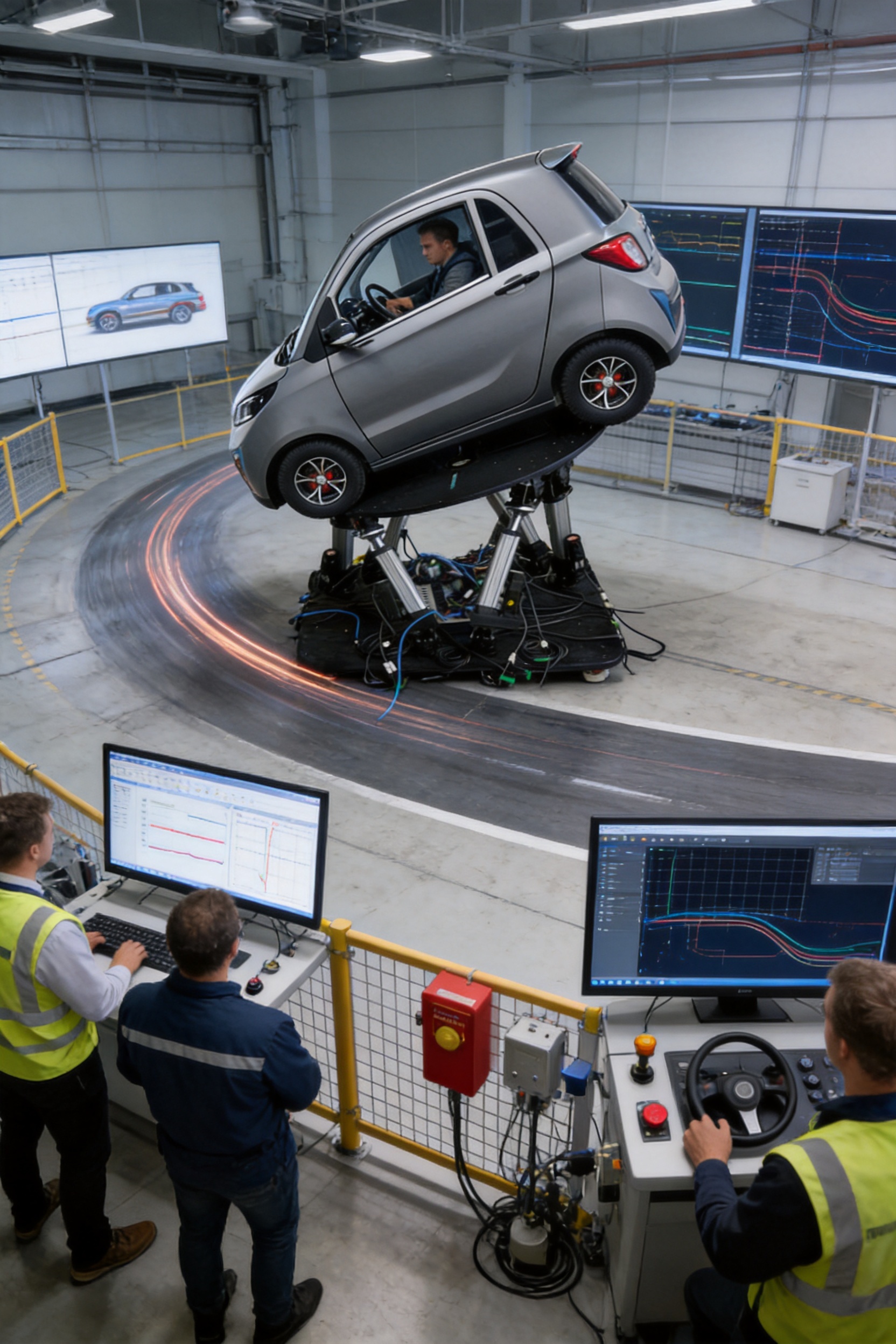
Before selecting a platform, buyers should first determine whether the application requires a full six-degree-of-freedom system or a smaller number of axes. If the test involves combined vehicle body motion, a six-axis platform is generally more suitable than a single-axis stage. If the application only requires vertical vibration or a simple linear stroke, a more focused system may be sufficient.
Payload is one of the most important selection factors. The calculation should include the vehicle or fixture mass, equipment mounted on the platform, passengers or test subjects where applicable, and dynamic loading. The center of gravity should also be provided because it affects actuator force and structural moment.
Travel and speed should be considered together. A large displacement at high speed requires more actuator power and may impose greater structural demands. Similarly, high acceleration with a heavy payload can require a larger motor, stronger joints, and a more rigid frame. Buyers should avoid selecting specifications independently without considering the complete motion profile.
Response frequency is another important factor. A platform intended for low-frequency vehicle attitude simulation may not require the same configuration as one intended for high-frequency vibration or road-input reproduction. The supplier should evaluate the desired frequency range, amplitude, payload, and control bandwidth as a combined requirement.
Finally, buyers should assess the software and integration requirements. Questions should include whether the system can import measured data, communicate with an external simulator, accept real-time commands, record motion data, provide APIs, support custom algorithms, and manage multiple test modes. Software flexibility can significantly affect the long-term value of the platform.
Commissioning should begin with an inspection of the foundation, frame, actuator connections, electrical cabinet, safety devices, cable routing, and grounding. The platform should be checked for shipping damage, loose fasteners, contamination, and mechanical interference.
The next step is a low-speed no-load or reduced-load movement test. This confirms axis direction, home position, limit switches, encoder feedback, and emergency-stop behavior. Operators should verify that the software coordinate system agrees with the physical motion of the platform.
After the basic checks, the platform can be tested with the intended fixture and payload. Motion should be increased gradually while monitoring motor current, position error, vibration, noise, temperature, and structural behavior. Any abnormal condition should be investigated before continuing.
Acceptance testing should compare the delivered system with the agreed technical specification. It may include travel measurement, speed measurement, acceleration measurement, angular range, positioning accuracy, repeatability, response testing, long-duration operation, communication verification, and safety-function testing.
Training should cover normal operation, test-profile creation, fault recovery, emergency procedures, basic maintenance, inspection intervals, and software backup. A well-trained operating team can improve productivity and reduce avoidable equipment damage.
Routine maintenance helps preserve accuracy and reliability. Ball screws and other transmission components should be lubricated according to the supplier’s recommendations. Joints, bearings, mounting bolts, cables, sensors, and protective devices should be inspected regularly.
Software and controller configurations should be backed up before major changes. Test profiles should be version-controlled so that engineers can identify which parameters were used for a particular result. Calibration records should be maintained, especially when the platform is used for regulated or research-critical testing.
Operators should pay attention to changes in noise, vibration, positioning error, motor temperature, response delay, and repeatability. These symptoms may indicate lubrication problems, mechanical wear, misalignment, sensor issues, servo-tuning changes, or structural loosening. Early investigation can prevent more serious failures.
The platform’s service life depends on how it is used. High payload, frequent high-acceleration operation, long daily operating hours, and harsh environments place greater demands on components. A lifecycle plan should include spare parts, maintenance intervals, technical support, software updates, and periodic performance verification.
6DOF means six degrees of freedom. In this platform, the six movements are pitch, roll, yaw, lateral displacement, longitudinal displacement, and vertical lift. These axes work together to reproduce complex vehicle motion.
Yes. Longitudinal motion and pitch can be coordinated to reproduce the vehicle attitude changes associated with acceleration and braking. The exact simulation result depends on the selected motion profile, payload, actuator configuration, and control algorithm.
Yes. The platform can coordinate lateral displacement, yaw, roll, and other axes to reproduce cornering, lane changes, obstacle avoidance, and other combined maneuvers. Test limits should be defined according to the payload and safety assessment.
It can be configured for different payloads and dimensions, including vehicle cabins, cockpit structures, component rigs, and other automotive test assemblies. A full-vehicle application requires detailed evaluation of mass, center of gravity, fixture design, motion envelope, structural strength, and foundation requirements.
Electric cylinders provide precise programmable motion, clean operation, digital feedback, and convenient integration with servo control systems. They also avoid the hydraulic oil circuit required by hydraulic actuators. The suitable actuator technology depends on load, speed, force, frequency, environment, and application requirements.
The control software is designed to reduce calibration requirements in suitable operating conditions through self-developed control algorithms. However, calibration and verification procedures may still be necessary for commissioning, major mechanical changes, new fixtures, high-accuracy testing, or applications with strict measurement requirements.
The exact interface depends on the project. The EtherCAT-based control architecture supports synchronized servo control, while optional software functions can be developed for external simulation systems, real-time commands, measured-data replay, special effects, and customized test management.
Safety is managed through a combination of mechanical structure, fixtures, travel limits, servo monitoring, emergency stops, protective guarding, software limits, operator procedures, and risk assessment. The final safety configuration should be designed for the specific test cell and payload.
Customers should provide the payload, platform size, center of gravity, required degrees of freedom, motion ranges, maximum speed, acceleration, frequency response, accuracy, operating cycle, power supply, test environment, software interface, fixture requirements, and safety expectations. Complete information allows the supplier to recommend a more accurate configuration.
Yes. Customization may include actuator size, motor power, screw dimensions, stroke, platform area, structural frame, mounting method, control cabinet, software, safety enclosure, communication interface, and data-acquisition functions.
The 6DOF Vehicle Dynamic Simulation Test Platform is a versatile tool for controlled, repeatable, and high-precision automotive motion testing. By combining pitch, roll, yaw, lateral displacement, longitudinal displacement, and vertical lift, it reproduces complex driving states more effectively than simple single-axis equipment. Its electric cylinders, high-dynamic ball screw transmission, EtherCAT control architecture, servo synchronization, and adaptable software provide a strong foundation for modern vehicle development.
The platform can help automotive organizations reduce dependence on early-stage road testing, improve test repeatability, enhance laboratory safety, and accelerate the evaluation of vehicle dynamics, chassis systems, driver behavior, and intelligent driving functions. Its value is further strengthened by a heavy-duty frame, multiple actuator configurations, high positioning precision, long-duration operating capability, and customization options for different payloads and motion envelopes.
Suzhou Tongyousheng Electronic Technology Co., Ltd. supports this product with capabilities in research and development, precision machining, actuator production, motion-control software, system integration, and customized automation engineering. Its broader experience in electric cylinders, linear motion products, servo presses, and multi-degree-of-freedom platforms enables it to approach vehicle simulation as a complete mechatronic system.
For customers planning a new automotive laboratory or upgrading an existing test facility, the most important step is to define the complete testing objective before selecting the equipment. When payload, motion, accuracy, frequency, software, safety, and installation requirements are evaluated together, a properly configured six-degree-of-freedom platform can become a long-term asset for vehicle engineering, research, validation, and innovation.
1. ISO 17206, Road Vehicles — Test Methods for Evaluating Vehicle Dynamic Performance.
2. ISO 6487, Road Vehicles — Measurement Techniques in Impact Tests.
3. International Electrotechnical Commission, IEC 61158, Industrial Communication Networks — Fieldbus Specifications.
4. International Electrotechnical Commission, IEC 61800, Adjustable Speed Electrical Power Drive Systems.
5. International Organization for Standardization, ISO 12100, Safety of Machinery — General Principles for Design — Risk Assessment and Risk Reduction.
6. International Organization for Standardization, ISO 13849, Safety of Machinery — Safety-Related Parts of Control Systems.
7. Gillespie, T. D., Fundamentals of Vehicle Dynamics, Society of Automotive Engineers.
8. Milliken, W. F. and Milliken, D. L., Race Car Vehicle Dynamics, Society of Automotive Engineers.
9. Shigley, J. E., Mechanical Engineering Design, McGraw-Hill.
10. Technical specifications and product information supplied for the 6DOF Vehicle Dynamic Simulation Test Platform.
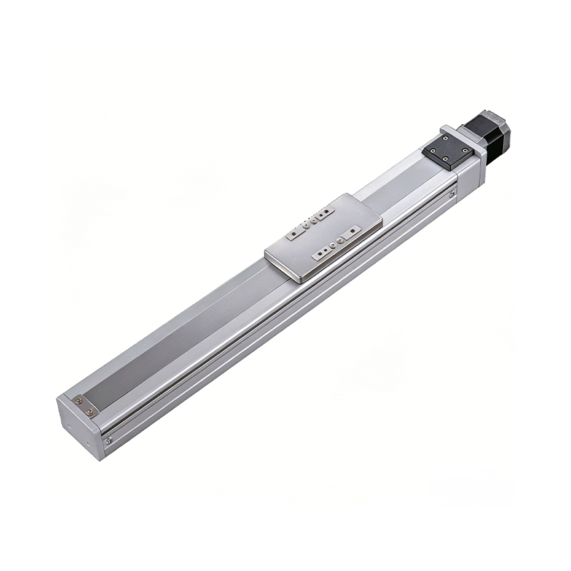 0.01mm High Precision Ball Screw Driven Rail-Embedded Linear Module
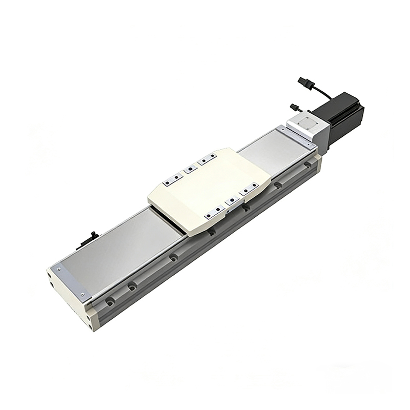 Heavy Load Ball Screw Driven Rail-Embedded Linear Module
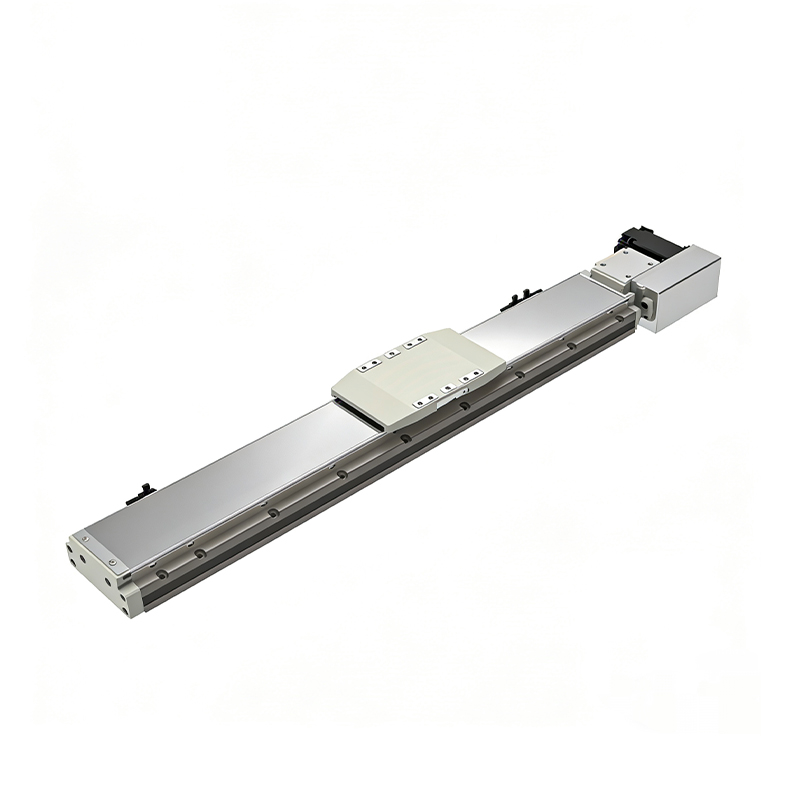 110KG Load Long Stroke Rail-Embedded Linear Module
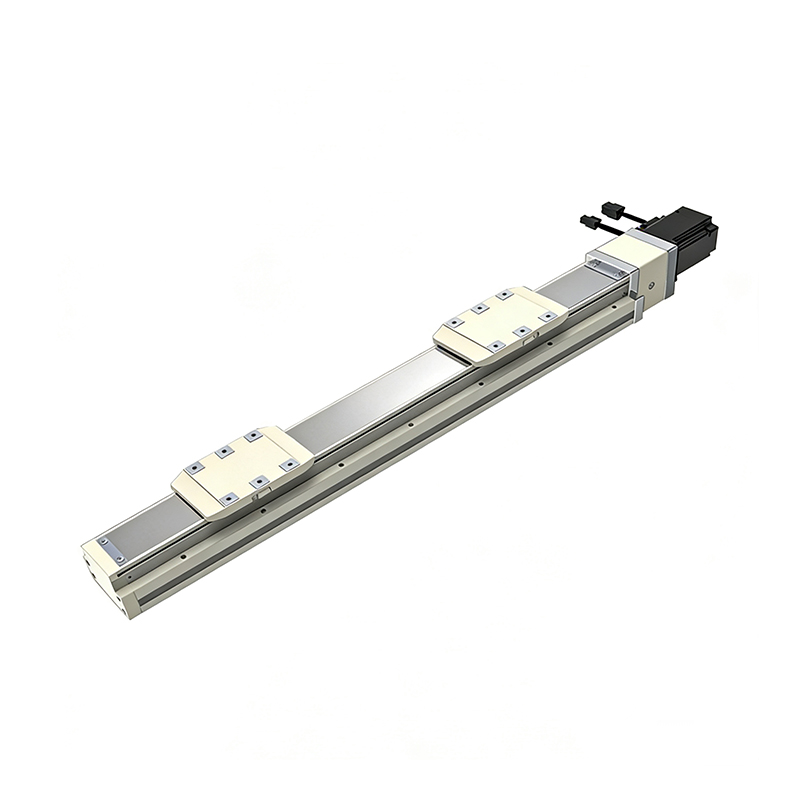 Dual-Slider High Precision Rail-Embedded Linear Module
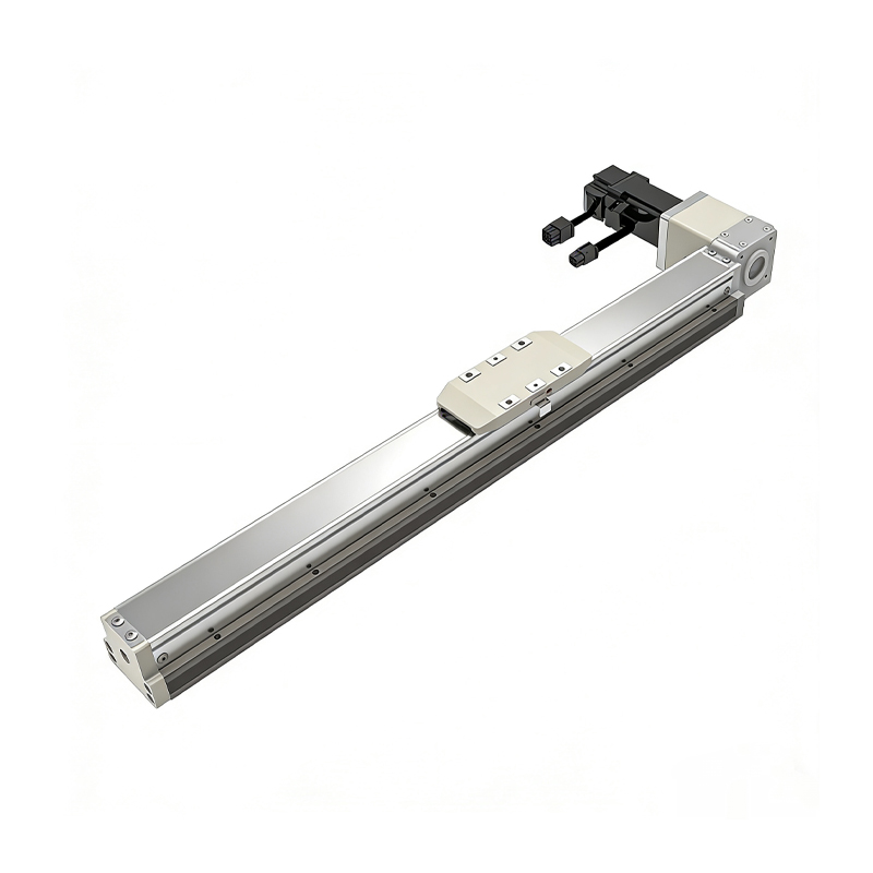 Belt Driven Dust-Proof Rail-Embedded Linear Module
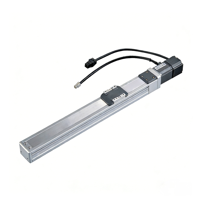 0.01mm High Precision Light Load Ball Screw Linear Module
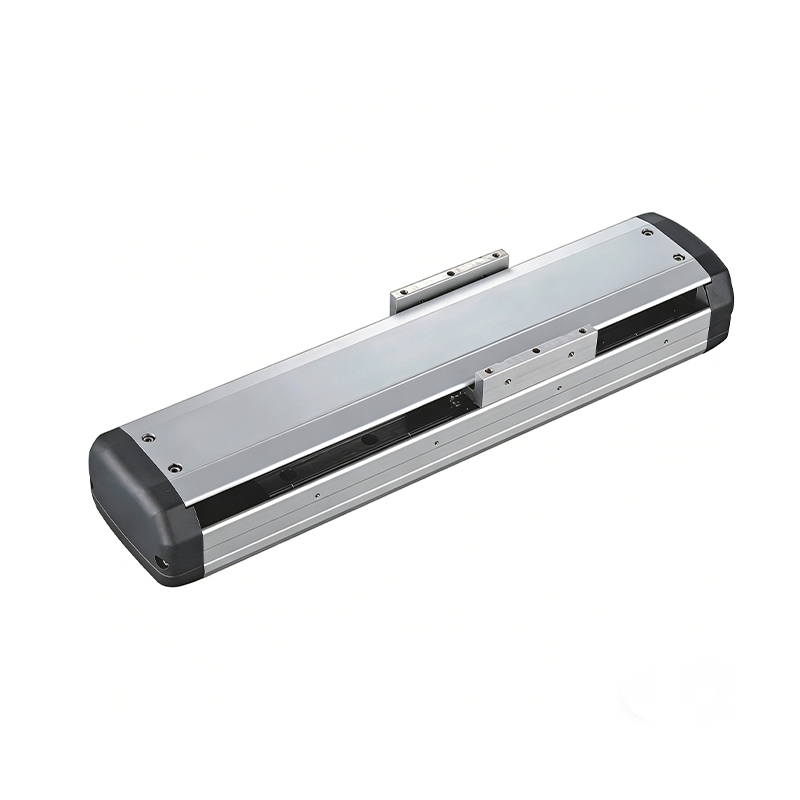 Ball Screw Linear Module with Built-in Sensor
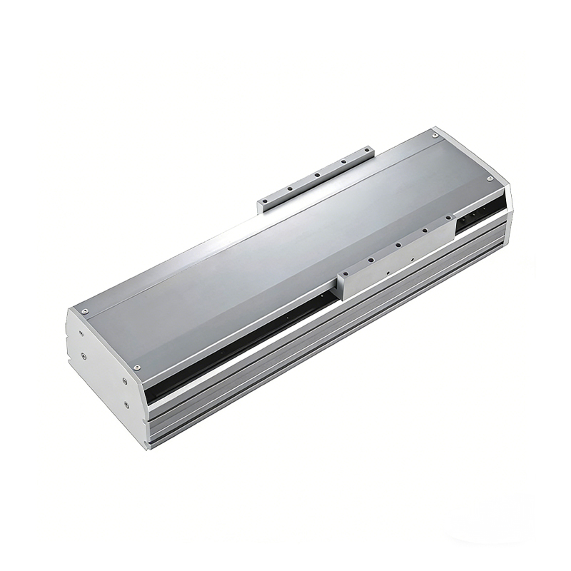 2000mm Long Stroke Ball Screw Linear Module
This 2000mm Long Stroke Ball Screw Linear Module is customized for large-range linear movement automation tasks, support...
READ MOREThis 2000mm Long Stroke Ball Screw Linear Module is customized for large-range linear movement automation tasks, support...
READ MOREThis 2000mm Long Stroke Ball Screw Linear Module is customized for large-range linear movement automation tasks, support...
READ MOREThis 2000mm Long Stroke Ball Screw Linear Module is customized for large-range linear movement automation tasks, support...
READ MORE
If you are interested in our products, please leave us a message. We look forward to providing you with
professional services!
Innovation and transcendence make factory intelligent manufacturing efficient and convenient!
+86 186 2508 0683
19962977901
sales@sz-tys.com
Building 5, Suzhou Mudu International Science and Technology Innovation Park, Jinfeng South Road, Suzhou City, Jiangsu Province, China
