


 English
 Français
 русский
 عربى
عربى Español
 Deutsch
Tel
+86 186 2508 0683

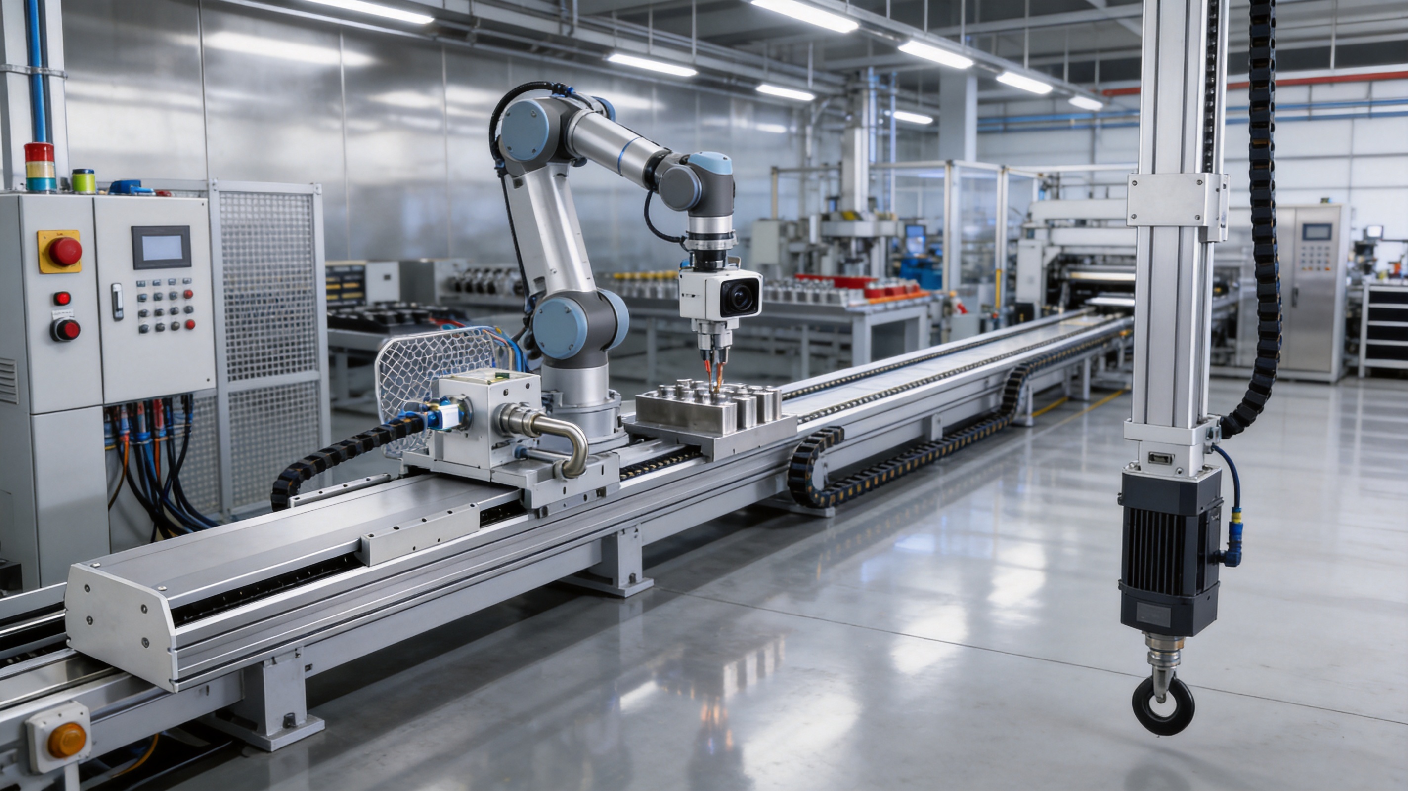
Long-stroke automation systems require more than simply extending the length of a conventional linear actuator. As the travel distance increases, the mechanical structure must maintain rigidity, the transmission system must resist deformation, and the guide mechanism must support stable movement under changing loads. At the same time, industrial users expect high repeatability, reliable operation, flexible installation, and compatibility with widely used servo motor systems.
The 2000mm Long Stroke Ball Screw Linear Module is designed for these demanding requirements. It is a high-rigidity ball screw linear motion solution developed for large-range positioning, material transfer, automated feeding, gantry equipment, CNC machinery, and other industrial applications requiring controlled linear movement over a long distance. The module supports a maximum effective stroke of 2000mm and combines a reinforced ball screw, high-rigidity linear guide, aluminum structural body, sensor systems, and AC servo motor options into an integrated motion platform.
Compared with many standard linear modules intended for short or medium travel, this product emphasizes structural stability over an extended working range. Its design helps reduce deflection and vibration during long-stroke movement while preserving a repeatability of ±0.01 mm. Multiple ball screw leads are available, allowing users to prioritize thrust, speed, or a balanced combination of both. Depending on the selected lead, the maximum listed speed ranges from 250 mm/s to 2000 mm/s, while horizontal payload capacity reaches up to 150 kg.
The module is manufactured and supplied by Suzhou Tongyousheng Electronic Technology Co., Ltd., a high-technology automation company specializing in electric cylinders, linear motion modules, linear motor modules, servo presses, robotic seventh axes, and multi-degree-of-freedom motion platforms. Its engineering capabilities extend from mechanical design and precision machining to motion integration, motor matching, and customized automation development.
This article examines the structure, performance, manufacturing strengths, competitive advantages, installation options, application value, and selection considerations of the 2000mm Long Stroke Ball Screw Linear Module.
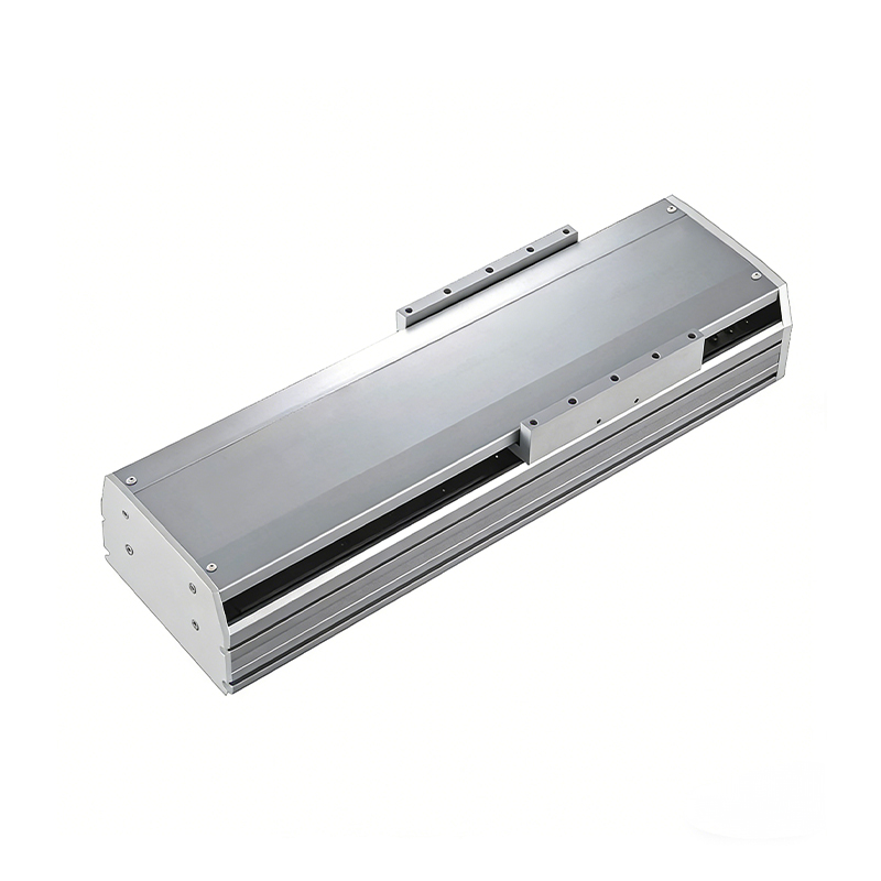
2000mm Long Stroke Ball Screw Linear Module
The primary purpose of this linear module is to deliver repeatable, controlled motion over a substantially long travel distance. A 2000mm stroke is suitable for moving workpieces, tools, fixtures, inspection systems, and processing heads across large work envelopes without requiring multiple short modules connected in series.
Using one integrated long-stroke module can offer several benefits compared with assembling several independent actuators. It reduces the number of mechanical interfaces, minimizes alignment work, simplifies cable routing, and avoids synchronization errors between separate axes. A single structural platform also provides a clearer load path from the moving carriage to the machine frame.
The module uses a ball screw transmission rather than a belt or rack-and-pinion system. Ball screw transmission is valued for its mechanical efficiency, high positioning capability, low backlash when correctly preloaded, and strong axial thrust performance. It is particularly suitable for applications in which the axis must repeatedly stop at precise positions or apply controlled pushing force.
The reinforced screw and guide structure are important for long-stroke operation. A long screw can be more sensitive to deflection, vibration, and critical-speed limitations than a short screw. The module therefore combines the transmission element with a high-rigidity guide rail and a robust body to support stable operation. Correct lead selection, acceleration control, mounting, lubrication, and load distribution remain essential, but the basic construction is intended for demanding industrial service.
The available stroke range is specified from 50 mm to 1500 mm in 50 mm increments in the supplied configuration tables, while the product description identifies a maximum effective stroke of 2000 mm. This indicates that the module can be customized or configured for long travel, with final dimensional confirmation required for each order. For applications requiring the full 2000 mm effective stroke, the overall module length, motor arrangement, sensor position, cable clearance, and installation envelope should be reviewed during technical selection.
The structural length varies according to the selected stroke and motor arrangement. For the motor-right, motor-left, and motor-bottom configurations, the listed body length is generally the selected stroke plus 382 mm. For the exposed-motor configuration, the listed length is generally the selected stroke plus 420 mm. The hidden-motor arrangement uses a longer structure, generally the selected stroke plus 590 mm. These values demonstrate why installation planning must consider more than the nominal travel distance.
The module provides a listed repeatability of ±0.01 mm. Repeatability describes the ability of the axis to return to a position under similar operating conditions. Actual performance may depend on motor encoder resolution, servo tuning, temperature, load distribution, mounting flatness, screw condition, lubrication, acceleration, and the measurement method used by the customer.
For precision automation, the machine frame should be sufficiently rigid and level. A high-performance module cannot compensate for a twisted mounting surface, uneven fastener torque, excessive overhang, or an improperly supported payload. The module is therefore best understood as one part of a complete motion system that includes the mechanical base, servo motor, drive, controller, sensors, and application software.
The following table summarizes the principal specifications provided for the 2000mm Long Stroke Ball Screw Linear Module. The ball screw lead determines the relationship between motor rotation and linear travel. A smaller lead generally provides higher thrust and lower maximum speed, while a larger lead supports faster travel with reduced mechanical advantage.
| Specification | Available Value or Range |
| Product type | Ball screw linear module |
| Maximum effective stroke | 2000 mm |
| Listed stroke selection | 50–1500 mm in 50 mm increments |
| Repeatability | ±0.01 mm |
| Ball screw leads | 5, 10, 25, and 40 mm |
| Maximum speed | 250, 500, 1250, or 2000 mm/s, according to lead |
| Maximum horizontal payload | 150, 150, 105, or 43 kg, according to lead |
| Maximum vertical payload | 55, 45, 20, or 12 kg, according to lead |
| Rated thrust | 2563, 1281, 640, or 320 N, according to lead |
| Ball screw | C7, diameter 25 mm or 20 mm |
| Linear guide | High-rigidity W23 × H20 guide |
| AC servo motor output | 750 W |
| Repeatability class | Application-dependent; listed module value ±0.01 mm |
| Typical service life | 10,000 km under normal use within catalog specifications |
| Static loading moments | MY: 2052 N·m; MP: 2052 N·m; MR: 1810 N·m |
| Sensor type | NPN-type outside and home sensors |
The module offers four principal lead options. The 5 mm lead provides the highest listed rated thrust of 2563 N and the highest vertical payload of 55 kg. Its maximum speed is 250 mm/s. This option is appropriate for applications emphasizing pushing force, controlled positioning, and heavier loads rather than rapid transfer.
The 10 mm lead offers a rated thrust of 1281 N, a maximum speed of 500 mm/s, a horizontal payload of 150 kg, and a vertical payload of 45 kg. It is a practical middle-range choice for many feeding, assembly, handling, and positioning applications.
The 25 mm lead increases maximum speed to 1250 mm/s. Its listed rated thrust is 640 N, with a horizontal payload of 105 kg and a vertical payload of 20 kg. This configuration is suitable when cycle time is important and the required force is moderate.
The 40 mm lead provides the highest listed maximum speed of 2000 mm/s. It has a rated thrust of 320 N, a horizontal payload of 43 kg, and a vertical payload of 12 kg. It is intended for high-speed horizontal transfer applications in which the moving mass and external resistance are carefully controlled.
These values should not be interpreted as independent guarantees that every combination of speed, payload, acceleration, and stroke can be used simultaneously. The actual duty cycle should be checked through a complete calculation that includes payload mass, center of gravity, friction, acceleration, deceleration, external force, installation direction, and required service life.
The maximum payload differs between horizontal and vertical installation. Horizontal installation offers the greatest listed capacity because the guide system primarily supports the load without continuously overcoming gravitational force. Vertical installation places additional demand on the ball screw, motor, brake, and control system.
Vertical applications may require a brake-equipped servo motor, particularly when the carriage must hold position during power loss or when the load could descend under gravity. The supplied motor options include no-brake versions for horizontal use and brake-equipped versions for vertical use. A safety assessment should determine whether a mechanical brake, counterbalance, secondary retention device, or other protective measure is necessary.
The main body is designed as a rigid support structure for the ball screw, linear guide, carriage, motor interface, and sensor components. The high-rigidity guide specification is W23 × H20, which indicates a guide structure designed to resist lateral forces and moment loads generated by the moving payload.
The static loading moment values are MY 2052 N·m, MP 2052 N·m, and MR 1810 N·m. These values represent the allowable or reference moments around the relevant axes under the stated catalog conditions. Because moment capacity depends strongly on the position of the payload center of gravity, the load should be mounted as close as practical to the carriage centerline.
A heavy payload located far above or away from the carriage creates a larger overturning moment than the same payload mounted close to the guide plane. This can affect accuracy, guide life, motor demand, and vibration. The supplied technical information notes that the torque values represent the center of gravity, so application designers should evaluate the actual center-of-gravity location rather than relying only on total mass.
Long-stroke travel magnifies the consequences of guide misalignment. A high-rigidity guide rail helps the carriage move smoothly while resisting pitch, yaw, and roll forces. This is especially important when the module carries an offset tooling plate, gripper, inspection camera, machining head, or secondary axis.
The guide system also helps distribute the payload along the body, reducing localized stress. However, the mounting surface must be prepared correctly. The base should be machined or otherwise controlled to provide a stable reference plane. Fasteners should be tightened in an appropriate sequence, and the axis should be checked for smooth motion throughout its travel before the servo is operated at full speed.
The ball screw is the central force-transmission component. Its rolling contact design offers high efficiency compared with sliding screw mechanisms, helping convert motor torque into linear thrust with relatively low friction. The C7 ball screw specification is commonly associated with a standard positioning accuracy grade suitable for many industrial automation tasks.
Ball screw performance depends on correct lubrication and protection from dust, chips, abrasive particles, and liquid contamination. In CNC or material-processing environments, protective covers, bellows, or enclosure arrangements may be required. Lubrication intervals should be based on operating speed, duty cycle, environment, and manufacturer recommendations.
Long ball screws can experience dynamic limitations at high rotational speeds. For that reason, the highest lead is not automatically the best choice for every 2000 mm application. A larger lead reduces the screw revolutions required for a given linear speed, but the resulting thrust is lower. The final selection should balance speed, thrust, payload, acceleration, and screw dynamics.
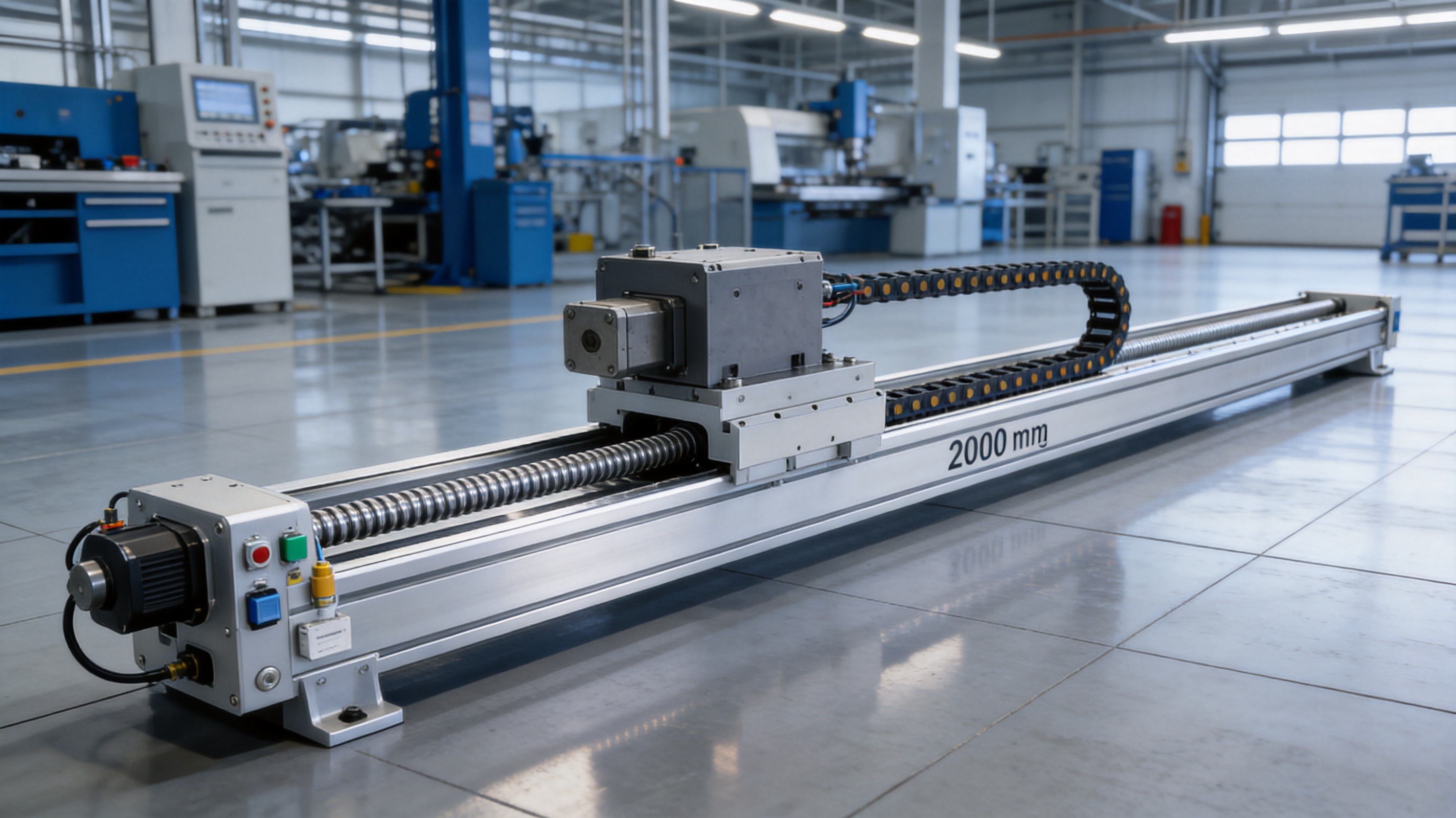
One of the main advantages of this product is its ability to provide long-range movement through an integrated module rather than a collection of loosely coordinated components. The integrated body, guide, screw, motor interface, sensor mounting, and carriage reduce the engineering effort required to create a complete linear axis.
Compared with conventional belt modules, a ball screw design can provide stronger thrust and more controlled positioning for force-demanding tasks. Compared with rack-and-pinion systems, it can reduce mechanical complexity at the axis level and support precise point-to-point positioning. Compared with multiple short modules joined together, it eliminates intermediate couplings that can introduce alignment errors or accumulated backlash.
The four lead options allow the same general product platform to address different requirements. A competitor offering only one fixed lead may force users to compromise between speed and thrust. Here, the user can select a 5 mm lead for high thrust, a 10 mm lead for balanced performance, a 25 mm lead for faster movement, or a 40 mm lead for high-speed transfer.
This flexibility is valuable for equipment manufacturers that build different machine models. The same basic module architecture can be adapted to feeding, assembly, loading, inspection, or processing tasks by changing the lead, motor arrangement, stroke, sensor position, and mounting orientation.
The listed horizontal payload reaches 150 kg for the 5 mm and 10 mm lead configurations. This supports substantial fixtures, workpieces, handling tools, and process equipment. Many compact linear stages prioritize low mass and high speed but cannot support heavy loads over a long travel. This module is positioned for users who need a stronger mechanical platform.
Heavy-load capability can reduce the need for additional support structures or parallel axes. It may also allow a single carriage to transport a complete tooling assembly, reducing the number of moving interfaces. The application must still account for acceleration and moment loads, but the available payload range provides a strong basis for industrial machine design.
The product structure tables identify motor-right, motor-left, motor-exposed, motor-bottom, and motor-hidden configurations. These orientations allow the actuator to fit different machine frames and cable-routing requirements.
A side-mounted motor can be useful where the top of the module must remain clear for a payload or secondary mechanism. A bottom-mounted motor can help reduce the overall side envelope. An exposed motor may simplify service access, while a hidden motor can provide a cleaner installation where the motor must remain within a protected machine space.
Motor orientation affects overall length, weight, service access, cable clearance, and mounting-hole accessibility. It should therefore be selected during the initial machine layout rather than treated as a late-stage accessory decision.
The module is designed around a 750 W AC servo motor and can be matched with servo systems from Mitsubishi, Panasonic, and Delta. This provides users with access to established industrial control ecosystems and makes it easier to integrate the axis into equipment using an existing preferred brand.
The listed Mitsubishi options include HG-KN73J-S100 for horizontal applications without a brake and HG-KN73BJ-S100 for vertical applications with a brake, paired with an MR-JE-70A driver. Panasonic options include MHMF082L1U2M without a brake and MHMF082L1V2M with a brake, paired with an MCDLN35SE driver. Delta options include ECM-B3M-C20807RS1 without a brake and ECM-B3M-C20807SS1 with a brake, paired with an ASD-B3-0721-L driver.
Motor and driver selection should be confirmed against the actual load, acceleration, speed, vertical holding requirement, control interface, and electrical standards of the machine. The availability of multiple brands is nevertheless a practical advantage for international integrators and replacement planning.
The module uses NPN-type sensors for outside and home detection. The listed outside sensor options are EE-SX672 NPN and FC-SPX303Z-2M NPN. The home sensor options are EE-SX674 NPN and FC-SPX307Z-2M NPN.
Home sensing establishes a repeatable machine reference after power-up or maintenance. Outside or end-of-travel sensing helps prevent the carriage from moving beyond the permitted range. In a complete control system, these sensors should be combined with servo drive limits, software travel limits, emergency-stop circuits, and suitable mechanical end protection.
Sensor positions should be checked against the selected stroke and motor arrangement. Cable routing must protect the sensor wires from abrasion, crushing, heat, moving chains, and electromagnetic interference. For high-cycle equipment, strain relief and appropriate flexible cable management are important for maintaining signal reliability.
Long-stroke axes may exhibit different dynamic behavior at different carriage positions. The moving mass, cable chain, payload, and structural resonance can influence servo response. Tuning should begin at conservative speed and acceleration values, followed by controlled optimization based on settling time, following error, vibration, and load behavior.
High-speed operation with a 25 mm or 40 mm lead should be validated over the full travel. It is not sufficient to test only the center of the axis, because end regions can respond differently depending on mounting, cable routing, and structural support. The machine builder should also verify that the emergency-stop sequence does not create excessive deceleration forces or payload movement.
Suzhou Tongyousheng Electronic Technology Co., Ltd. was established in 2013 and has developed capabilities in research, design, production, sales, and automation system integration. Its portfolio includes electric cylinders, linear modules, linear motor modules, servo presses, robotic seventh axes, six-degree-of-freedom platforms, and other motion-control equipment.
The company’s manufacturing strength is based on the integration of mechanical engineering, electrical control, precision machining, product assembly, and application support. This integrated approach is important for long-stroke motion products because performance is not determined by a single component. The ball screw, guide, body, coupling, motor, sensor, controller, and mounting interface must work as one coordinated system.
The company maintains an experienced research and development team supported by advanced design software. Computer-aided mechanical design enables engineers to evaluate structural dimensions, motor arrangements, mounting patterns, carriage configurations, and installation envelopes before production.
Engineering analysis is particularly valuable for customized long-stroke products. Customers may require unusual motor orientations, special payload interfaces, nonstandard sensor positions, customized cable routing, or integration with a robotic system. A strong design process allows these requirements to be assessed systematically rather than handled as improvised modifications.
Advanced CNC machining centers are used to produce precision mechanical parts and structural components. Controlled machining helps maintain the dimensional consistency needed for guide installation, screw alignment, bearing support, motor mounting, and carriage movement.
Precision machining is also important for repeatability between production batches. When automation equipment is installed at multiple factories, consistent mechanical interfaces simplify commissioning, spare-part planning, and maintenance. Controlled machining practices can reduce variation in mounting surfaces and improve the predictability of final assembly.
Assembly quality directly affects the performance of a linear module. Guide rails and ball screws must be installed with appropriate alignment and preload. Couplings must be properly centered, and the servo motor should be connected without introducing angular or parallel misalignment. Sensors must be located accurately so that the home and limit positions correspond to the actual machine travel.
A reliable manufacturing process therefore includes inspection of machined parts, verification of component fit, controlled assembly, functional testing, and review of motion performance. For a long-stroke module, inspection should cover the full travel range rather than only a short sample movement.
The stated service life is 10,000 km under normal use and compliance with catalog specifications. This figure depends on correct installation, lubrication, payload, speed, acceleration, operating environment, and maintenance. It represents a useful design reference but should not replace an application-specific life calculation.
The company collaborates with state-owned enterprises, defense technology institutions, and universities to promote the integration of industry, academia, and research. Such cooperation can strengthen the development of motion algorithms, structural design methods, control software, and application-specific equipment.
This background supports the company’s ability to serve both standard-product customers and users requiring customized automation. The product can function as an individual axis, but it can also become part of a larger intelligent manufacturing system involving robotics, inspection, pressing, simulation, or coordinated multi-axis motion.
The supplied structure tables provide dimensional information for several motor arrangements and stroke selections. For many configurations, the selected stroke is available in 50 mm increments. The body length, mounting-hole pattern, number of mounting positions, and product weight change with the selected travel.
For motor-right and motor-left arrangements, the listed body length starts at 432 mm for a 50 mm stroke and increases by 50 mm as the selected stroke increases by 50 mm. At a 1500 mm stroke, the listed length is 1882 mm. The associated weight increases from approximately 24.2 kg to 66.54 kg.
For the exposed-motor arrangement, the listed length starts at 470 mm for a 50 mm stroke and reaches 1920 mm for a 1500 mm stroke. The weight ranges from approximately 25.4 kg to 67.74 kg. The greater length reflects the motor arrangement and associated structure.
For the hidden-motor configuration, the listed length ranges from 640 mm at a 50 mm stroke to 2090 mm at a 1500 mm stroke. Weight ranges from approximately 27.85 kg to 70.48 kg. This configuration may be attractive when protection and compact motor presentation are more important than minimum overall length.
When the stroke is 50 mm, the top-locking mounting holes on the main body may be blocked by the slider. In that condition, only four screws can be used for fixation through the affected mounting arrangement. The supplied instructions recommend using the bottom-locking mounting holes to secure the main body.
This detail illustrates the importance of reviewing the mechanical drawing before installation. Short travel does not necessarily mean simple installation. The slider occupies a larger proportion of the body at very short strokes, and access to fasteners may be restricted. Machine builders should ensure that tools can reach all required fasteners and that the selected mounting method provides sufficient rigidity.
Allowable overhang data is provided for horizontal, wall-mounted, and vertical installations. The tables relate lead selection to allowable dimensions identified as A, B, and C. These values help engineers determine how far the payload or center of gravity may extend from the supported carriage under specific installation conditions.
Overhang is one of the most important factors in long-stroke design. A payload with a high center of gravity or a large distance from the guide plane creates a moment that can increase carriage deflection and guide loading. Even when the total mass is below the stated payload, excessive overhang can reduce practical performance.
Horizontal installation generally permits larger allowable dimensions than vertical installation because gravity acts differently on the guide and screw. Wall-mounted use has its own load distribution and may require attention to fastener shear, support spacing, and machine-frame rigidity.
The catalog notes that standard specifications do not apply to ceiling-mounted inverted use. Customers requiring an inverted or ceiling-mounted configuration should contact the sales team for technical confirmation. This limitation should be treated seriously because inverted installation changes lubrication behavior, load paths, safety risks, and the way the carriage is retained during power loss.
The module is suitable for feeding workpieces, trays, containers, components, or packaging materials across extended distances. Its ball screw transmission provides controlled indexing and repeatable stops, while the long stroke allows one axis to serve multiple processing stations.
For feeding systems, the 5 mm or 10 mm lead may be selected when the payload is heavy or when the axis must resist pushing forces. If the items are lightweight and cycle time is the priority, the 25 mm or 40 mm lead may be more appropriate.
In gantry systems, a long linear module can serve as the horizontal travel axis for a gripper, lifting unit, or processing head. The high-rigidity guide and substantial horizontal payload capacity support the movement of large fixtures or workpieces.
When two parallel modules are used in a gantry, the machine builder must carefully synchronize the axes and control their parallelism. Alternatively, the module may act as the primary travel axis while a separate vertical or transverse axis performs the remaining movement.
The module can be applied to long-travel CNC processing machines, loading systems, drilling equipment, cutting machinery, and automated tool movement. In environments containing chips, dust, coolant, or abrasive materials, the ball screw and guide should be protected by suitable covers or enclosures.
Processing forces may be more demanding than simple transfer loads. The engineer should evaluate cutting forces, vibration, tool offset, thermal changes, and dynamic stiffness. The module’s rated thrust and moment values provide a starting point, but final suitability depends on the specific process.
A long-stroke linear module can function as a robotic seventh axis, allowing a robot to travel along a production line or access several workstations. The module’s extended stroke can increase the robot’s operating envelope without requiring a larger fixed robot.
In robotic applications, the dynamic behavior of the robot and carriage should be considered together. Robot acceleration can generate changing moments, especially when the arm is extended. Cable management, emergency stopping, protective guarding, and coordinated controller communication are also essential.
The precise, repeatable travel of a ball screw module is useful for moving cameras, sensors, probes, laser heads, or test fixtures. The axis can scan long components, inspect multiple positions, or position a measurement device over a large test area.
Inspection systems may benefit from the 10 mm or 25 mm lead, depending on the required positioning force and scanning speed. If measurement accuracy is critical, the complete system should be calibrated after installation, including the module, fixture, sensor, and control software.
Before installation, confirm the selected stroke, motor orientation, mounting pattern, sensor type, payload, installation direction, and available clearance. The machine base should be sufficiently rigid to prevent distortion when the module is bolted down.
During installation, avoid forcing the module into alignment with an uneven frame. The mounting surface should support the body continuously or at the recommended mounting locations. Fasteners should be tightened evenly, and the carriage should be moved manually or at low speed to identify binding before full commissioning.
Lubrication is essential for both the ball screw and linear guide. The lubricant type and interval should be selected according to the operating environment and duty cycle. Excessive contamination can shorten service life, while insufficient lubrication increases friction, heat, wear, and noise.
Maintenance inspections should include checking for abnormal sound, increased backlash, inconsistent positioning, temperature rise, loose fasteners, cable damage, sensor failure, and lubricant deterioration. If the axis operates in a dusty, wet, or high-cycle environment, inspections should be performed more frequently.
The stated guaranteed service life is 10,000 km when the product is used normally and in compliance with catalog specifications. Actual service life can be improved by reducing shock loads, avoiding excessive overhang, maintaining correct lubrication, using suitable acceleration profiles, and protecting the transmission from contamination.
Long-stroke linear modules can store significant kinetic and gravitational energy. Guarding should prevent personnel from entering hazardous travel zones during operation. Emergency-stop circuits should be designed to stop the axis safely without creating an uncontrolled payload shift.
Vertical installations require special attention. A brake-equipped motor may help hold the carriage, but the machine risk assessment should determine whether additional mechanical retention is necessary. The module should not be used as the sole safety device for suspended loads unless the complete system has been designed and validated for that purpose.
Start by defining the required effective stroke, not merely the distance between two process points. Include approach distance, deceleration distance, sensor clearance, mechanical end protection, and any required overtravel margin.
Next, determine the total moving mass. This includes the workpiece, fixture, gripper, motorized tooling, cable chain, brackets, and any secondary axes mounted on the carriage. Calculate the center-of-gravity position and resulting moments, not only the static weight.
Select the installation direction: horizontal, wall-mounted, vertical, or another arrangement. Ceiling-mounted inverted use requires separate technical confirmation. For vertical movement, determine whether the motor requires a brake and whether an additional holding mechanism is appropriate.
Choose the ball screw lead according to the required speed and thrust. The 5 mm lead is appropriate for high thrust and slower controlled motion. The 10 mm lead is a balanced choice for many general applications. The 25 mm lead is suitable for faster motion with moderate force. The 40 mm lead is intended for high-speed transfer with lower payload and thrust requirements.
Confirm the motor brand and drive compatibility. Existing factory standards may favor Mitsubishi, Panasonic, or Delta. The machine controller, encoder interface, electrical supply, communication protocol, and brake wiring should be reviewed before ordering.
Finally, select the motor orientation and sensor layout based on the machine envelope. The shortest nominal length may not be the best overall solution if it creates difficult maintenance access or interferes with cable routing.
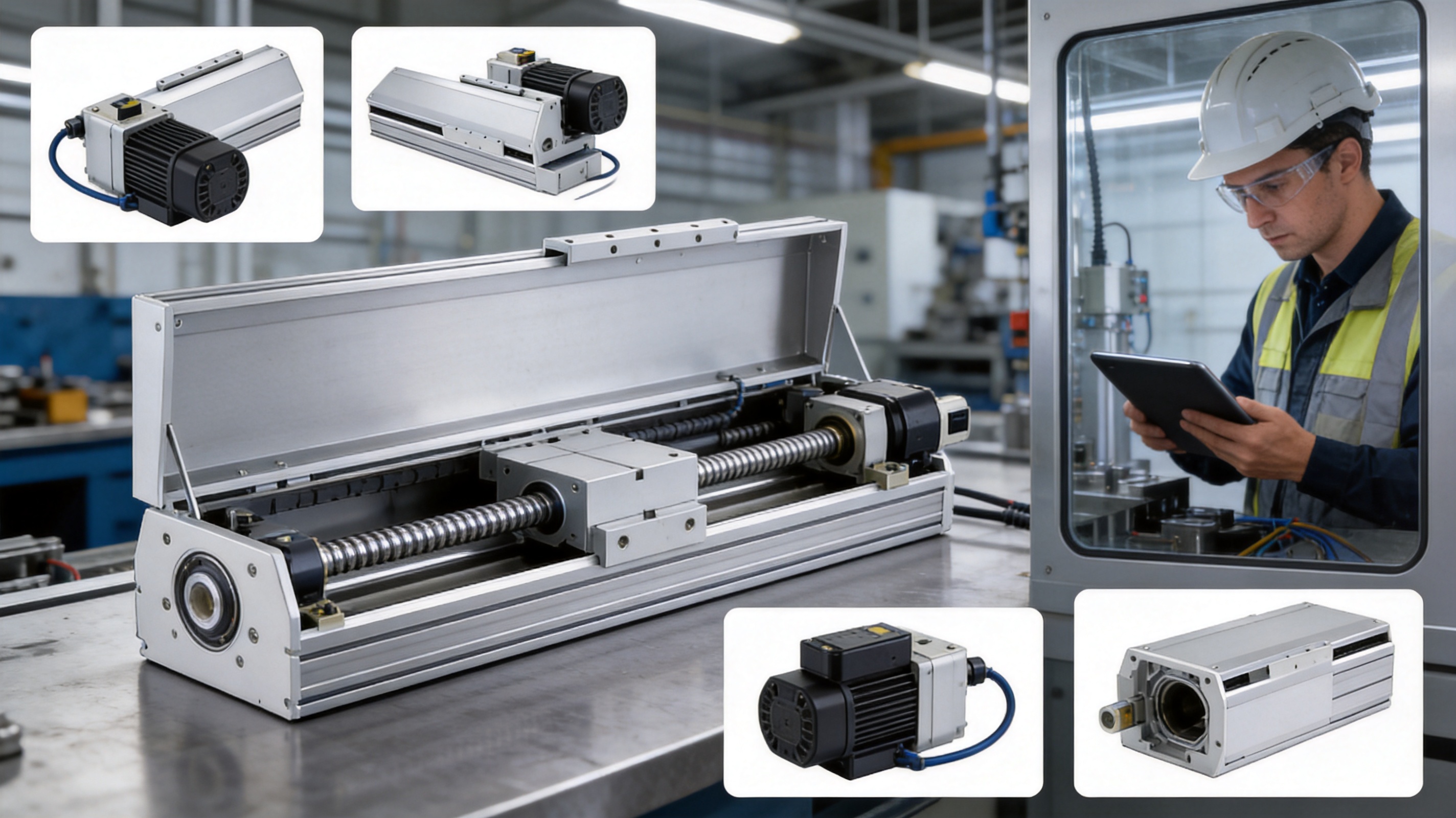
The 2000mm Long Stroke Ball Screw Linear Module combines long travel, high payload capability, multiple transmission ratios, several motor orientations, and compatibility with established servo brands. This combination reduces the need to compromise between mechanical strength and system flexibility.
Its main advantage over basic short-stroke actuators is the ability to support a large working envelope within one coordinated mechanical assembly. Its advantage over belt-driven long axes is the emphasis on thrust and controlled positioning. Its advantage over individually assembled components is the reduced integration burden and greater consistency between the guide, screw, motor interface, and sensors.
The company’s experience in electric cylinders, servo presses, linear modules, robotic axes, and multi-degree-of-freedom platforms further supports the product’s use in complete automation solutions. Customers can obtain not only a motion component but also assistance with configuration, motor matching, control integration, and customized equipment development.
For original equipment manufacturers, the availability of standard stroke increments and multiple structure configurations can shorten development time. For end users, the module offers a practical path toward upgrading manual transfer operations, expanding robot work envelopes, or creating automated loading and inspection processes.
The product description identifies a maximum effective stroke of 2000 mm. The supplied dimensional tables list standard stroke selections from 50 mm to 1500 mm in 50 mm increments. The exact configuration for a 2000 mm effective stroke should be confirmed with the supplier because total body length and motor arrangement affect the final design.
The listed repeatability is ±0.01 mm. Actual system performance depends on servo resolution, tuning, mechanical installation, temperature, payload, acceleration, lubrication, and measurement conditions.
The 5 mm lead provides the highest listed rated thrust, 2563 N, and the highest listed vertical payload, 55 kg. It also has the lowest maximum speed of 250 mm/s.
The 40 mm lead provides the highest listed maximum speed, 2000 mm/s. Its rated thrust is 320 N, and its horizontal and vertical payload ratings are lower than those of the smaller-lead configurations.
Yes, vertical installation is listed, but the payload and performance ratings differ from horizontal installation. A brake-equipped servo motor may be required, and the complete system should be evaluated for gravitational loads, power-loss behavior, emergency stopping, and safety retention.
Standard specifications do not apply to ceiling-mounted inverted use. Customers requiring this arrangement should obtain specific technical confirmation before selecting or installing the product.
The listed options include Mitsubishi, Panasonic, and Delta 750 W AC servo motors and their compatible drivers. Both brake and no-brake versions are identified for different installation requirements.
The supplied information identifies NPN-type outside and home sensors. Outside sensor options include EE-SX672 NPN and FC-SPX303Z-2M NPN. Home sensor options include EE-SX674 NPN and FC-SPX307Z-2M NPN.
The guaranteed service life is stated as 10,000 km under normal use and in compliance with catalog specifications. Correct installation, lubrication, load management, protection from contamination, and suitable acceleration profiles are required.
It is described as suitable for long-stroke CNC processing machines and related automation. CNC applications should include appropriate protection from chips, coolant, dust, and cutting debris, together with a detailed evaluation of process forces and vibration.
Users should confirm the required stroke, total moving mass, center of gravity, installation direction, overhang, speed, acceleration, thrust, lead, motor brand, brake requirement, sensor type, mounting orientation, cable routing, and environmental protection requirements.
The 2000mm Long Stroke Ball Screw Linear Module is designed for industrial automation tasks requiring reliable linear travel across a large working range. Its reinforced ball screw, high-rigidity guide, substantial horizontal payload capacity, ±0.01 mm listed repeatability, and multiple lead choices make it suitable for applications ranging from automated feeding and gantry handling to CNC loading, robotic seventh axes, inspection, and intelligent manufacturing systems.
The module’s competitive value comes from the combination of long-stroke capability and configuration flexibility. Users can select different leads to balance speed and thrust, choose several motor orientations to fit machine layouts, and pair the axis with Mitsubishi, Panasonic, or Delta servo systems. Detailed structure tables, sensor options, moment ratings, and allowable overhang data support more systematic machine design.
Equally important is the manufacturing and engineering foundation behind the product. Suzhou Tongyousheng Electronic Technology Co., Ltd. combines research and development, precision CNC machining, component assembly, motion-control integration, and customized automation experience. Its broader work with electric cylinders, servo presses, robotic axes, and multi-degree-of-freedom platforms supports the development of complete and application-specific motion solutions.
For machine builders seeking a robust long-range axis, the product offers a strong platform for designing faster, more precise, and more adaptable automation equipment. Proper configuration and installation remain essential, but when selected according to the actual payload, moment, speed, environment, and safety requirements, this ball screw linear module can provide dependable service in demanding industrial applications.
1. Product specification materials for the 2000mm Long Stroke Ball Screw Linear Module, including performance tables, structure dimensions, sensor information, motor options, and installation notes.
2. Internal technical information concerning ball screw linear modules, high-rigidity linear guides, allowable overhang, static loading moments, and service-life conditions.
3. Servo motor and servo driver selection information for Mitsubishi, Panasonic, and Delta 750 W AC servo systems.
4. General engineering principles for ball screw selection, linear guide loading, moment calculation, servo-axis commissioning, and industrial automation safety.
5. Corporate information regarding Suzhou Tongyousheng Electronic Technology Co., Ltd., its research and development activities, CNC machining capabilities, automation product portfolio, and Industry 4.0 applications.
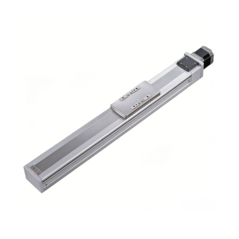 0.01mm High Precision Ball Screw Driven Rail-Embedded Linear Module
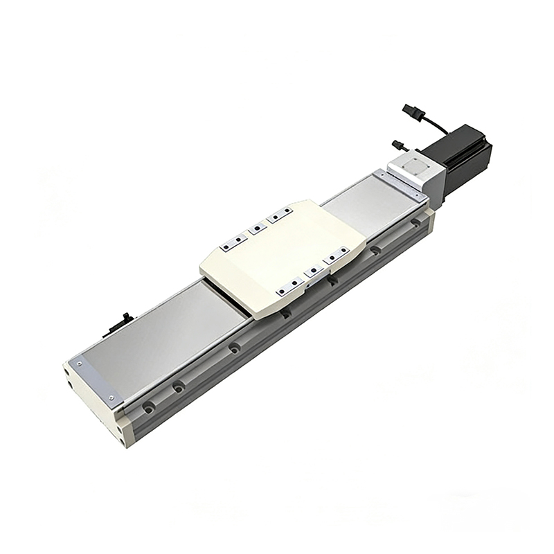 Heavy Load Ball Screw Driven Rail-Embedded Linear Module
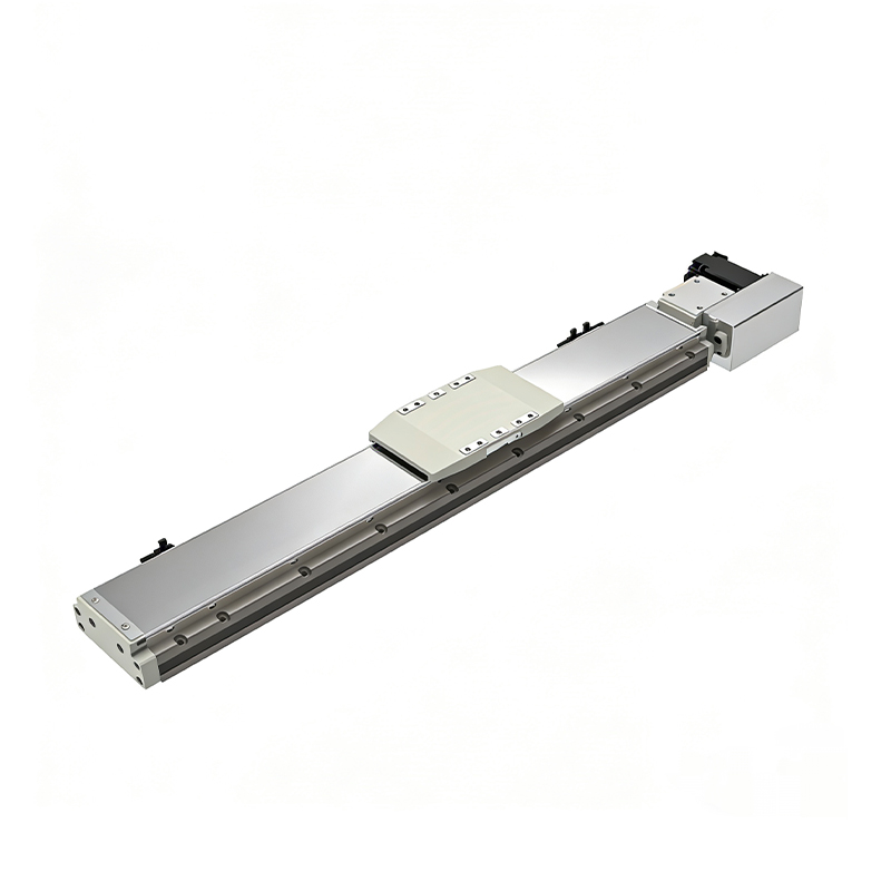 110KG Load Long Stroke Rail-Embedded Linear Module
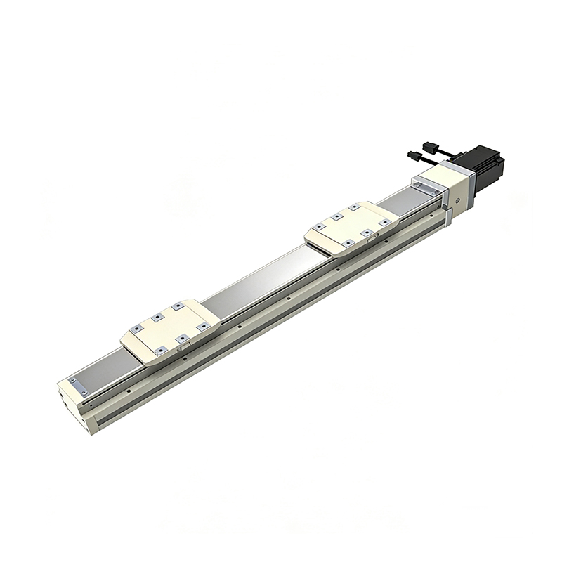 Dual-Slider High Precision Rail-Embedded Linear Module
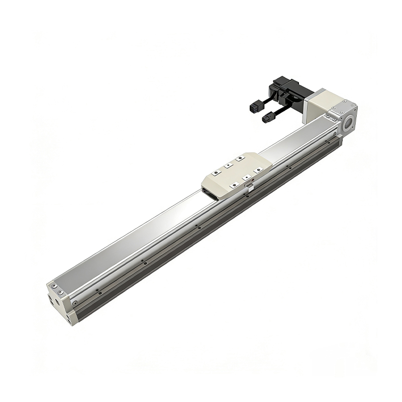 Belt Driven Dust-Proof Rail-Embedded Linear Module
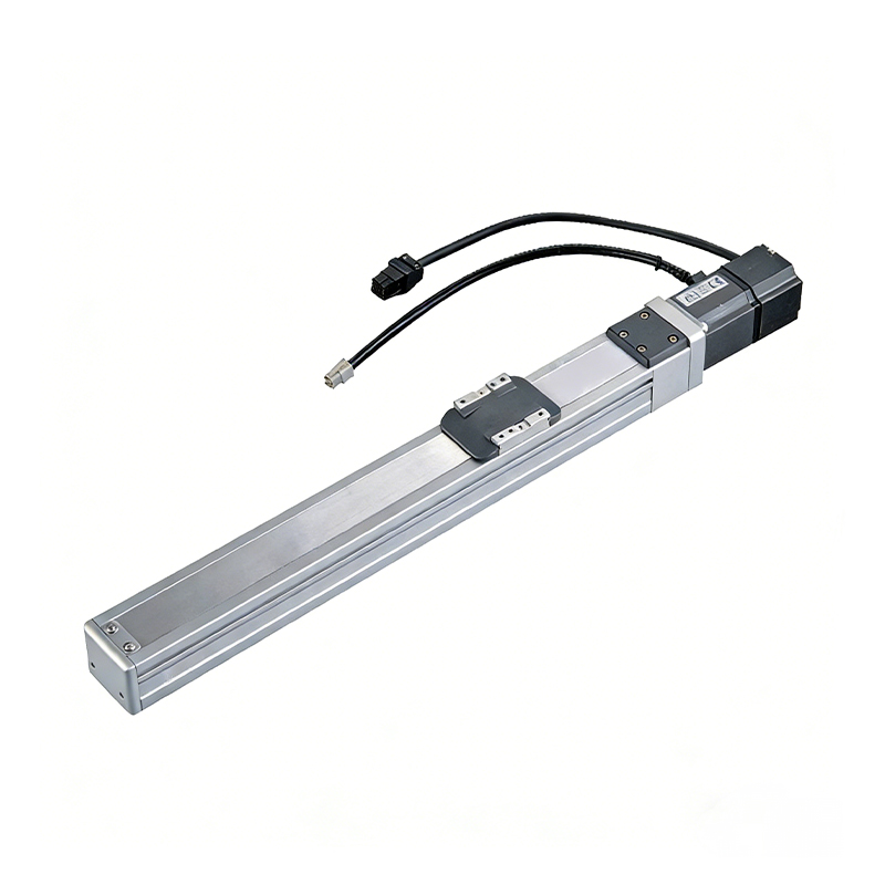 0.01mm High Precision Light Load Ball Screw Linear Module
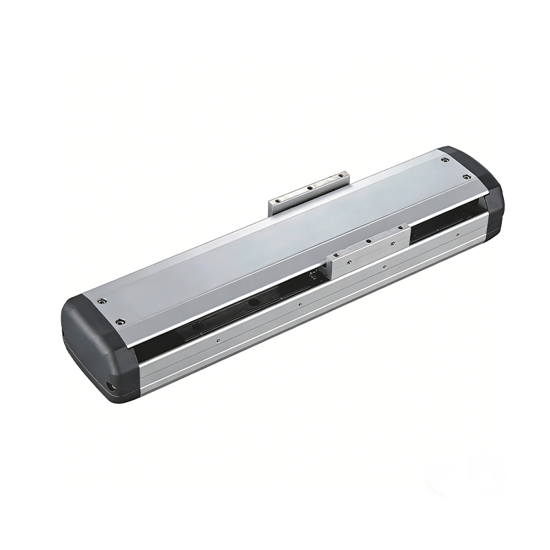 Ball Screw Linear Module with Built-in Sensor
2000mm Long Stroke Ball Screw Linear Module
Ball Screw Linear Module with Built-in Sensor
2000mm Long Stroke Ball Screw Linear Module
This 2000mm Long Stroke Ball Screw Linear Module is customized for large-range linear movement automation tasks, support...
READ MOREThis 2000mm Long Stroke Ball Screw Linear Module is customized for large-range linear movement automation tasks, support...
READ MOREThis 2000mm Long Stroke Ball Screw Linear Module is customized for large-range linear movement automation tasks, support...
READ MOREThis 2000mm Long Stroke Ball Screw Linear Module is customized for large-range linear movement automation tasks, support...
READ MORE
If you are interested in our products, please leave us a message. We look forward to providing you with
professional services!
Innovation and transcendence make factory intelligent manufacturing efficient and convenient!
+86 186 2508 0683
19962977901
sales@sz-tys.com
Building 5, Suzhou Mudu International Science and Technology Innovation Park, Jinfeng South Road, Suzhou City, Jiangsu Province, China
