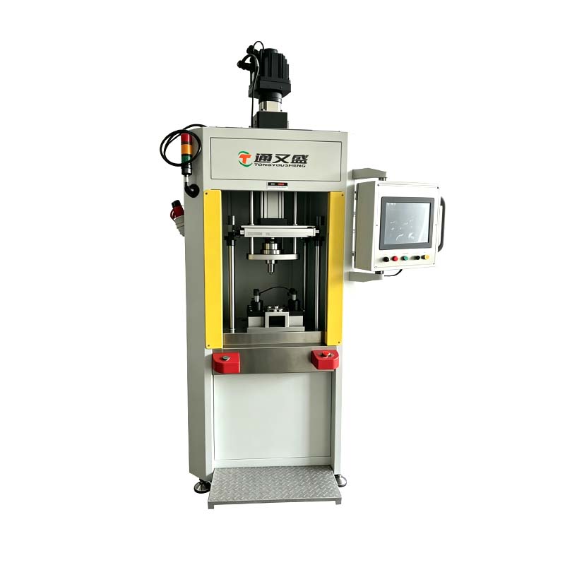
Servo Press Machine: Curve Segmentation and Force Calibration Decisions Behind the Scenes
A bearing supplier switched from a fixed-stop pneumatic press to an servo press machine after seeing a 3% rejection rate on outer-race seating depth. The new press solved the depth problem within the first week, but a different issue surfaced almost immediately — the operators had copied the single-segment force curve from their old pneumatic setup, and the press was accepting parts that a trained assembler would have flagged as suspect just by feel. The curve had one target force and one tolerance band, which meant it couldn't tell the difference between a smooth, gradual seating and a part that jammed halfway through, spiked, then slid the rest of the way in.
Why One Segment Rarely Tells the Whole Story
A press-fit force curve carries information at every point along the stroke, not just at the end. Bearing seating typically shows a rising force as the outer race engages the housing bore, then a brief plateau or slight dip as the race clears a chamfer, then a final rise as it seats against a shoulder. If the acceptance criteria only look at peak force, a part that jammed on the chamfer and then broke free with a spike can still land within the peak force window even though something went wrong mid-stroke. Splitting the curve into segments — approach, initial engagement, mid-stroke transition, final seating — lets each phase carry its own force and slope tolerance, catching problems that a single number would miss entirely.
Matching Segment Count to Assembly Complexity
The number of segments needed isn't fixed — it tracks the number of distinct mechanical events the part goes through during assembly. A simple shaft-into-bushing press might only need two segments: an approach zone with a loose tolerance and a final seating zone with a tight one. A multi-stage assembly, like a gear pressed onto a splined shaft with a retaining clip engaging partway through, might need four or five segments because each mechanical event — spline engagement, clip snap-over, final shoulder contact — produces its own signature on the curve that needs independent verification.
| Assembly Type |
Typical Segment Count |
What Each Segment Verifies |
| Simple shaft/bushing fit |
2 segments |
Approach clearance, final seating force |
| Bearing race seating |
3 segments |
Initial engagement, chamfer transition, shoulder seating |
| Multi-component stack with clip or snap feature |
4-5 segments |
Each mechanical event isolated for independent pass/fail check |
Segmentation Without Overloading the Process
There's a practical ceiling on how finely a curve should be split. Too many segments and the tolerance windows start overlapping process noise — normal part-to-part variation in surface finish or lubrication gets flagged as a fault even when the assembly is sound. Too few segments and genuine defects slip through undetected. Getting this balance right on an electric servo press usually comes from running a sample batch first, plotting the curve family across dozens of known-good parts, and setting segment boundaries where the curves naturally diverge from each other rather than at arbitrary stroke positions. Suzhou Tongyousheng Electronic Technology Co., Ltd. works through this segmentation exercise with customers during process setup, using sample runs from the actual production part rather than a generic reference curve.
Where Force Calibration Fits Into the Picture
None of this segmentation logic matters if the force reading itself can't be trusted, which raises a separate but related question: how does the press confirm that a reading of, say, 850 newtons actually corresponds to 850 newtons of real force at the tooling interface. Some presses ship with force calibration based purely on the load cell's factory datasheet and the drive's torque-to-force conversion formula — a reasonable starting point, but one that doesn't account for friction losses in the ball screw, minor drift in the load cell over time, or mounting-induced offset from the specific tooling installed on that unit.
Standard Load Cell Verification as a Separate Step
A more reliable approach runs a calibrated reference load cell through the press's full force range before shipment, comparing the press's internal reading against the reference at multiple points across the stroke rather than trusting a single calculated conversion factor. Suzhou Tongyousheng Electronic Technology Co., Ltd. performs this verification with a traceable reference load cell on units before they leave the facility, which catches discrepancies that a purely calculated force output would miss — particularly on longer-stroke units where screw friction isn't perfectly uniform from one end of travel to the other.
| Calibration Method |
What It Accounts For |
Limitation |
| Factory preset conversion only |
Nominal drive torque and screw lead |
Misses friction variation and load cell drift |
| Reference load cell verification |
Actual measured force at multiple stroke points |
Adds a verification step before shipment |
Why This Matters Once the Press Reaches the Assembly Line
A curve segmented correctly but calibrated against a calculated rather than measured force baseline can still pass parts that would fail under real-world tolerance, or reject parts that were actually fine — the segmentation logic is only as trustworthy as the numbers feeding it. This is why a buyer evaluating an servo press machine for a critical press-fit application should ask both questions together: how the curve will be segmented for their specific assembly sequence, and whether the force values reported by the press have been checked against a calibrated reference rather than assumed from the motor's torque constant alone.
The bearing supplier mentioned earlier resolved their issue by reworking the curve into three segments matched to the actual mechanical events in the seating process, and by requesting calibration verification data for the specific unit installed on their line — a combination that brought the rejection rate down without adding cycle time to the station.



 English
 Français
 русский
 عربى
عربى Español
 Deutsch